Controller / User Interface | 4-9
General Tab
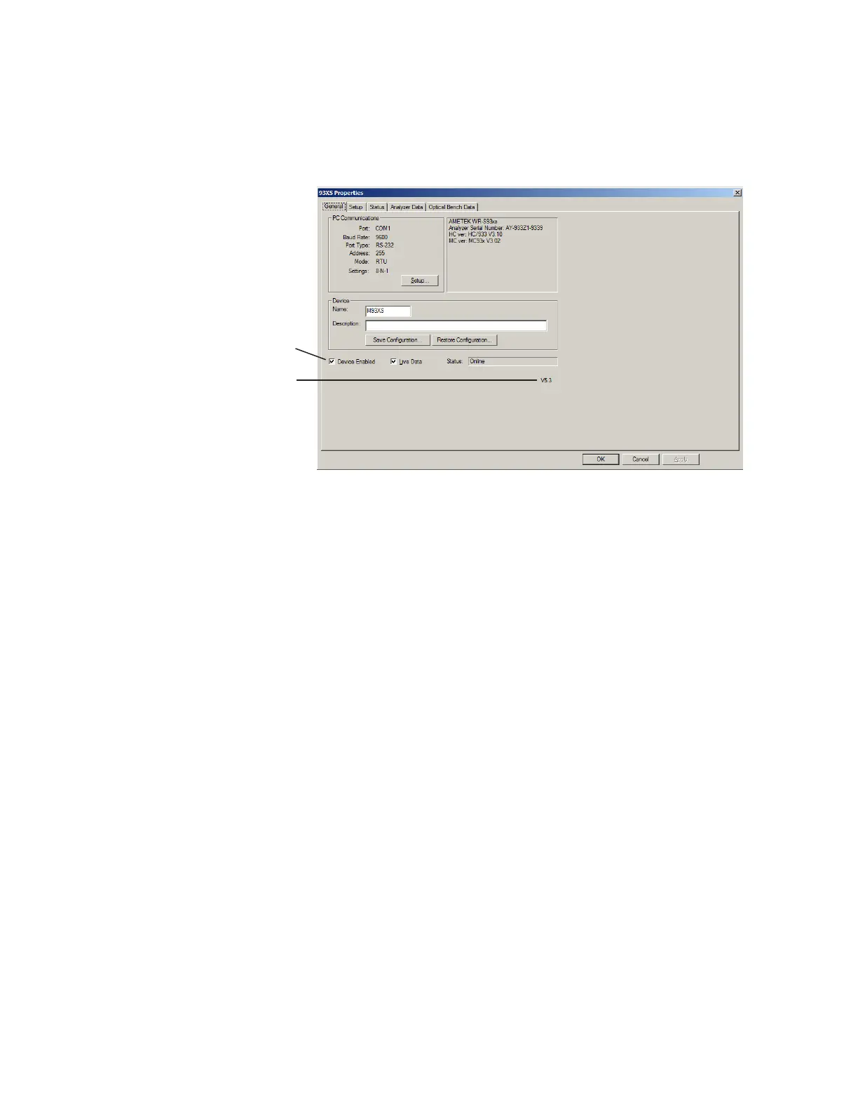
When the analyzer is connected to the PC, the current Host Control-
ler and Microcontroller Firmware Version Number and analyzer Serial
Number are displayed to the right of PC Communications (Figure 4-1).
Figure 4-1.
General tab.
Congurator Software Version
Check box selected
Other parameters include:
PC Communications
Displays information that has been configured from the Communica-
tion Settings dialog box.
Setup
Allows you to set up the communication parameters required to
establish communication with the analyzer (see “Modbus Serial /
Modbus TCP Communication Setup” in this chapter).
Device
Name
Enter a tag name or number.
Description
Enter a description to further define the analyzer, such as a Tag
Number or location in the plant.
This can be useful if using a Multi-Drop system, where multiple
analyzers are wired together on the same line. In this case, you can
assign different names and descriptions for each analyzer.
 Loading...


