Home
Ametek
Measuring Instruments
933S
Ametek 933S User Manual
5
of 1
of 1 rating
288 pages
Give review
Manual
Specs
To Next Page
To Next Page
To Previous Page
To Previous Page
Loading...
Appendix
A
– Drawings
|
A-5
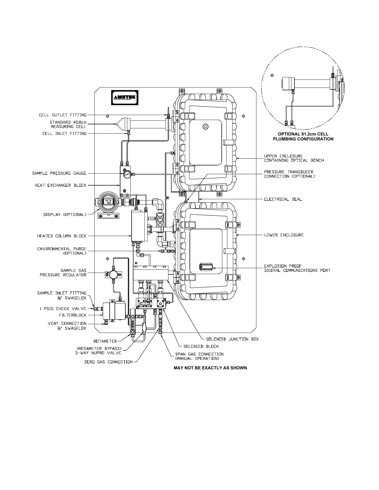
Backpan Component Layout, North
American Style (WX-933NA-3A)
SERIAL COMMUNICATIONS PORT
DO NOT OPEN IF A HAZARDOUS
GAS ATMOSPHERE IS PRESENT
MAY NOT BE EXACTLY AS SHOWN
PROCESS INSTRUMENTS
REFERENCE CERTIFICATION NO: CSA CERTIFICATE 1031027 (LR48179)
62.78
PLUMBING CONFIGURATION
OPTIONAL 81.2cm CELL
268
270
Table of Contents
Default Chapter
2
Offices
2
Table of Contents
3
Electrical Safety
8
Grounding
8
Safety Notes
8
Personnel and Equipment Safety Information
9
Warnings
9
Cautions
10
Warning Labels
11
Environmental Information
11
UV Source Lamps Disposal
11
Electromagnetic Compatibility (EMC)
12
Special Warnings and Information
13
Equipment Used in Class I, Division 2 Hazardous Locations
13
EU Declaration of Conformity
14
Warranty and Claims
16
Chapter 1 Overview
17
About the Analyzer
18
About the Analyzer Sample System
20
Working in this Manual
22
Supplemental Information - Where Can I Find It
23
Chapter 2 Specifications
25
Methodology
25
Full-Scale Ranges
25
Standard Range Measuring Cells (40 CM or Smaller)
25
Low Range Measuring (White) Cell Option (81.2 CM)
25
Response Time
26
Accuracy
26
Repeatability
26
Calibration
26
Linearity
26
Stability
26
Sensitivity
27
Cross-Talk
27
Temperature Drift
27
24-Hour Zero Drift
27
Customer Connections
28
Analog Outputs
28
Digital Communication
28
Digital Inputs
28
Electrical Requirements
28
Maximum Start-Up Power
28
Supply Voltage / Maximum Current
28
Sample Gas Flow Rate
28
Zero Gas
29
Ambient Limits
29
Temperature
29
Humidity
29
Maximum Altitude
29
Sample Pressure Requirement
29
Sample Stream Compatibility
30
Maximum Sample Gas Temperature
30
Maximum Sample Cell Pressure
30
Physical Dimensions (on Backpan)
30
Options
30
Carbon Dioxide Sensor
31
Accuracy
31
Cross-Talk
31
Temperature Drift
31
24-Hour Zero Drift
31
Approvals and Certifications
32
ATEX and Iecex Certificates and Analyzer Markings
33
CSA Certificate and Analyzer Marking
41
Chapter 3 Installation and Start-Up
47
Safety Considerations
48
Pre-Installation Requirements
48
Storage Prior to Installation
48
Uncrating and Inspecting the Analyzer
49
General Installation Information
50
Tools and Equipment Required
50
Installing the Mechanical Components
51
Installing the Analyzer
51
Location and Environment
51
Installing the Optical Bench Assembly
53
Installing the Sample System
55
Installing the Sample and Vent Lines
55
Installing the Sample Probe
55
Installing the Zero Gas Line
57
Electrical Connections
58
Input/Output Signal Connections
58
Digital Communication
59
Hardware Configuration (Modbus Serial Communication)
59
Multiple-Analyzer (Multi-Drop) System Configuration
63
AC Power Connection and Fusing
65
European Installation
66
North American Installation
66
S93XS System 200 Configurator Software Installation
68
Minimum PC Requirements for Configurator Software
68
Installing the S93XS System 200 Configurator Software
69
Removing the Configurator Software
71
Start-Up and Verification
72
Powering up the Analyzer
72
Start-Up Diagnostic Checklist
82
Sample System Leak Check
84
Sample Conditioning System Optimization
87
Column Switch Time Optimization
87
Hold Time Optimization
92
Chapter 4 Controller / User Interface
95
System 200 Configurator Software Overview - Getting Started
96
Navigating in the Software
96
Starting the Configurator Software and Establishing Communication between the Analyzer and Computer
98
Closing the Configurator Software
100
Configurator Software Troubleshooting
101
General Tab
103
Modbus Serial / Modbus TCP Communication Setup
105
User Interface
108
Setting up the Main Window
108
Viewing Device Activities
109
Restoring Analyzer Configuration Parameters
110
Saving Analyzer Configuration Parameters
110
Modifying Analyzer Device Settings
112
Working from the Setup Tab
112
Printing Analyzer Configuration Parameters
115
Saving Analyzer Configuration Parameters to an ASCII File
115
Refreshing Configuration or Calibration Parameters
116
Saving Configuration or Calibration Parameters to EEPROM
116
Optical Bench
117
Cell/Miscellaneous (Compensations) Parameters
122
Temperature Control
125
Optical Bench Temperature Control
127
Measuring Cell (Oven) Temperature Control (Optional)
128
Column Block Temperature Control
130
Output Setup
131
Sensors Setup
134
Modbus Settings
140
Matrix
141
Analytical Parameters
142
Analog Inputs
143
Setting Gas Calibration Parameters
145
Alarm Setting and Stream Switch Parameters
150
Analyzer Information
153
Column Timing
155
Viewing Analyzer Data
156
Status Tab
156
Analyzer Data Tab
162
Optical Bench Data Tab
164
Chapter 5 Calibration
165
Calibrating the Analyzer and Gas Sensors
166
Analog Output Calibration
172
Current Calibration
172
Voltage Calibration
174
Chapter 6 Maintenance and Troubleshooting
177
Safety Considerations
177
Preventive Maintenance
179
Analyzer Preventive Maintenance Schedule
180
Preventing, Detecting, and Locating a Plug in the Sample System
182
Changing out Replaceable Parts
184
Measuring Cell Maintenance
185
Column Block Maintenance
194
Source Lamp Replacement
201
When Do Source Lamps Need to be Replaced
201
About the Source Lamps
202
Replacing the Source Lamps
202
When Is an Auto-Setup Required / Not Required
210
PMT Level and PMT Balance
211
Auto-Setup Fault Message and Corrective Action
212
The Auto-Setup Sequence
212
Cancel Auto-Setup
213
Manipulating the PMT Level and PMT Balance
214
Source Lamp Alignment
216
Natural Gas Filterblock Maintenance
218
Filtration Stages
219
Vent Flow
219
Replacing Parts in the Filterblock
220
Chopper Assembly Maintenance
225
Examining and Caring for the Flamepaths
233
Upper/Lower Electronics Enclosure Flamepaths (Joining Surfaces)
235
Troubleshooting and Diagnostics
236
Host Controller Board Alarm Conditions and Corrective Action
238
Microcontroller Board Alarm Conditions and Corrective Action
247
Analyzer Reset
256
Chapter 7 Service and Parts
257
Technical Support
257
Returning Equipment
258
AMETEK SERVICE and AFTERMARKET SALES SUPPORT
259
Recommended Preventive Maintenance Spare Parts
260
Optical Bench/Sample System Spare Parts
260
Spare Analyzer Fuses
262
Replacement Boards
263
Ordering a Hard Copy of the Analyzer Operator's Guide
263
Appendix A - Drawings
265
Block Diagram, European Style (WX-933ATEX-1
266
Block Diagram, North American Style
267
Sample Flow Diagram (Plumbing Schematic), North American Style
268
Backpan Component Layout, North American Style (WX-933NA-3A
269
Backpan Dimensions, North American Style
270
Conduit Entries, I/O and AC Power Connection Locations, North American Style (WX-933NA-3B
271
Lower Enclosure Layout (WX-14838
272
Customer Connections Wiring Schematic, North American Style/120 VAC
273
Communications Cable Connections (300-9480
274
Analyzer Wiring Diagram (WX-102860-1
275
TC Sensor Wiring Diagram (WX-102860-2
276
IR Sensor Wiring Diagram (WX-102860-3
277
Optional HMI and Ethernet Gateway Wiring Diagram (WX-102860-4
278
Optical Bench Board (P/N 100-1662
279
PMT Buffer Board (100-0140
280
Sample Probe - North American/European Style
281
Sample Probe, Recommended Mounting Details - North American (CSA)/ European (Zone 1/ATEX
282
Solenoid Block, North American Style (100-1791-1A
283
Solenoid Block, European Style (100-1917-1A
284
Inlet and Vent Flame Arrestor Locations, Environmental Purge Option (100-1783-1A
285
Backpan Component Layout, Division 2 Analyzer with Sensor (Example
286
Supplemental Information
287
5
Based on 1 rating
Ask a question
Give review
Questions and Answers:
Need help?
Do you have a question about the Ametek 933S and is the answer not in the manual?
Ask a question
Ametek 933S Specifications
General
Brand
Ametek
Model
933S
Category
Measuring Instruments
Language
English
Related product manuals
Ametek 930
256 pages
Ametek 932S
268 pages
Ametek 900
256 pages
Ametek 303B
70 pages
Ametek IPS-4
238 pages
Ametek 3050 Series
86 pages
Ametek Reichert 7CR
48 pages
Ametek BROOKFIELD DVPlus
80 pages
Ametek SPECTRO ARCOS FHX22
55 pages
Ametek Land Cyclops L Series
60 pages
Ametek mocon Dansensor ISM-3
34 pages
Thermox Series 2000 WDG-IV
193 pages