5-8 | Model 933S UV Analyzer
Analog Output Calibration
Current Calibration
The current outputs are calibrated at the factory. If a current output
module is replaced or added, calibrate that output. This is done from the
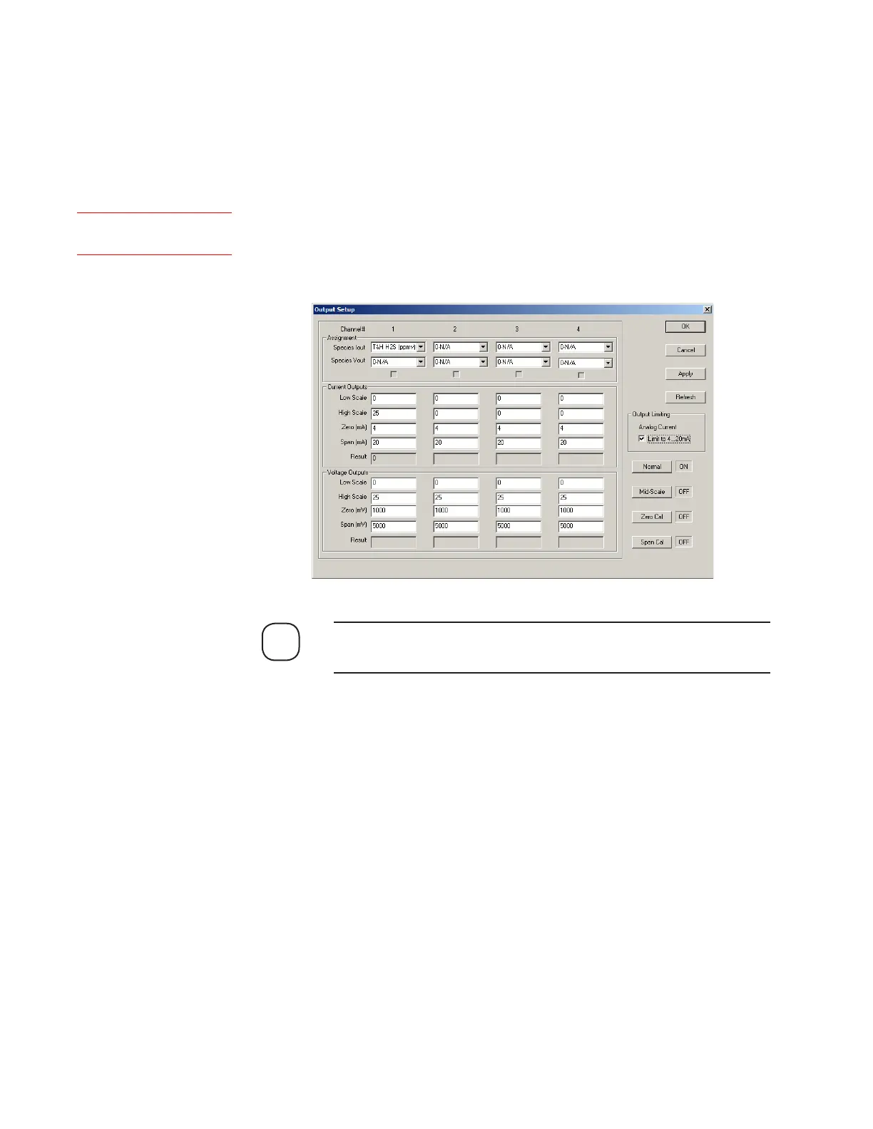
Output Setup dialog box. Calibration of a current output is performed by
entering the measured low-scale (Zero) and full-scale (Span) signals for
each output (see Figure 5-5). These values are used to offset the output to
the correct values.
NOTE
When performing current or voltage calibration, do not enable (check)
Limit 4...20 mA after calibration is complete.
To calibrate the current outputs:
1. Measure the Zero (low-scale) signal of each output:
a. Click the Zero Cal button to change its status to On. The status of
Normal, Mid-Scale, and Span Cal should be Off.
b. Connect a current meter to Pins 1 and 2 (at J109 on the Customer
I/O board) and measure the current of Output 1. Under Current
Outputs, enter the value next to Zero (mA), under the first column
(Output 1). Place a 250 Ohm resistor in series of the multi-meter for
accurate calibration.
Repeat this step for Output 2 (Pins 3 and 4), Output 3 (Pins 5 and 6),
and Output 4 (Pins 7 and 8), recording the value for each output in
the corresponding field.
Figure 5-5.
Output Setup dialog
box.
Setup (tab)Output
 Loading...


