Overview | 1-3
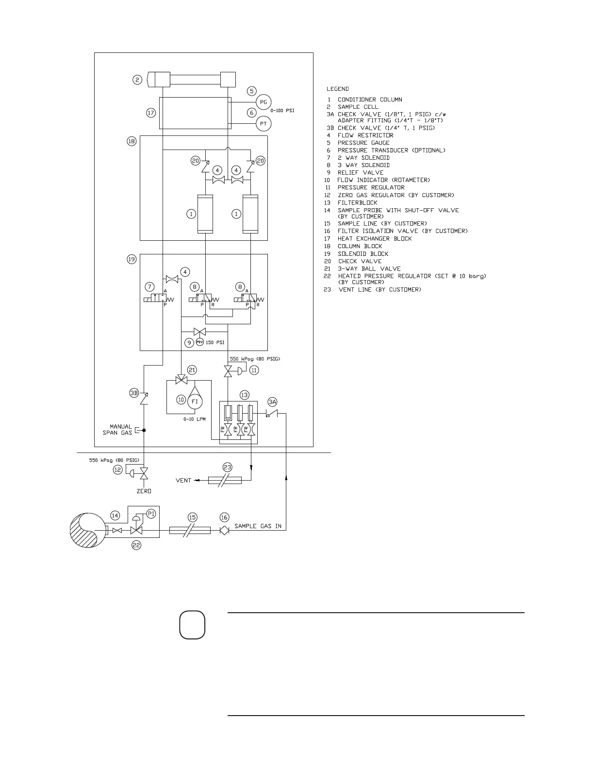
Figure 1-2 illustrates a Sample Flow Diagram (plumbing schematic)
for a typical European style analyzer. See Appendix A for a North
American style drawing, or see the Final “As-Built” drawings, if
ordered, in the analyzer Documentation Package.
The Vent Line should vent to atmospheric or < 0.5 PSI. Refer to Final
“As-Built” drawings for actual drawing for your system.
NOTE
Figure 1-2.
Sample ow diagram
(Plumbing Schematic).
 Loading...


