3-8 | Model 933S UV Analyzer
4. Connect the wiring connectors to the Micro-Interface board:
• Measuring Cell RTD line to J300.
• RS-422 communication line to J104.
• Micro-Interface AC power line to J200.
• DC power line to J103.
• Optional: If your analyzer has a Cell Heater, connect the Heater
Cartridge wire (marked ‘N’) to J200 (Terminal 2) and the Overtemp
Switch wire (marked ‘L’) to J200 (Terminal 1).
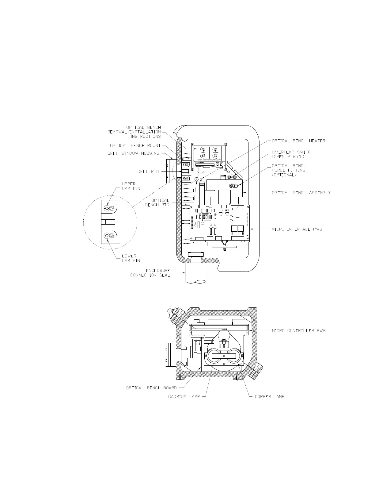
Figure 3-2.
Upper Enclosure
layout and Cam Pin
locations.
 Loading...


