3-28 | Model 933S UV Analyzer
b. Upon power-up, all solenoids will remain de-energized for at least
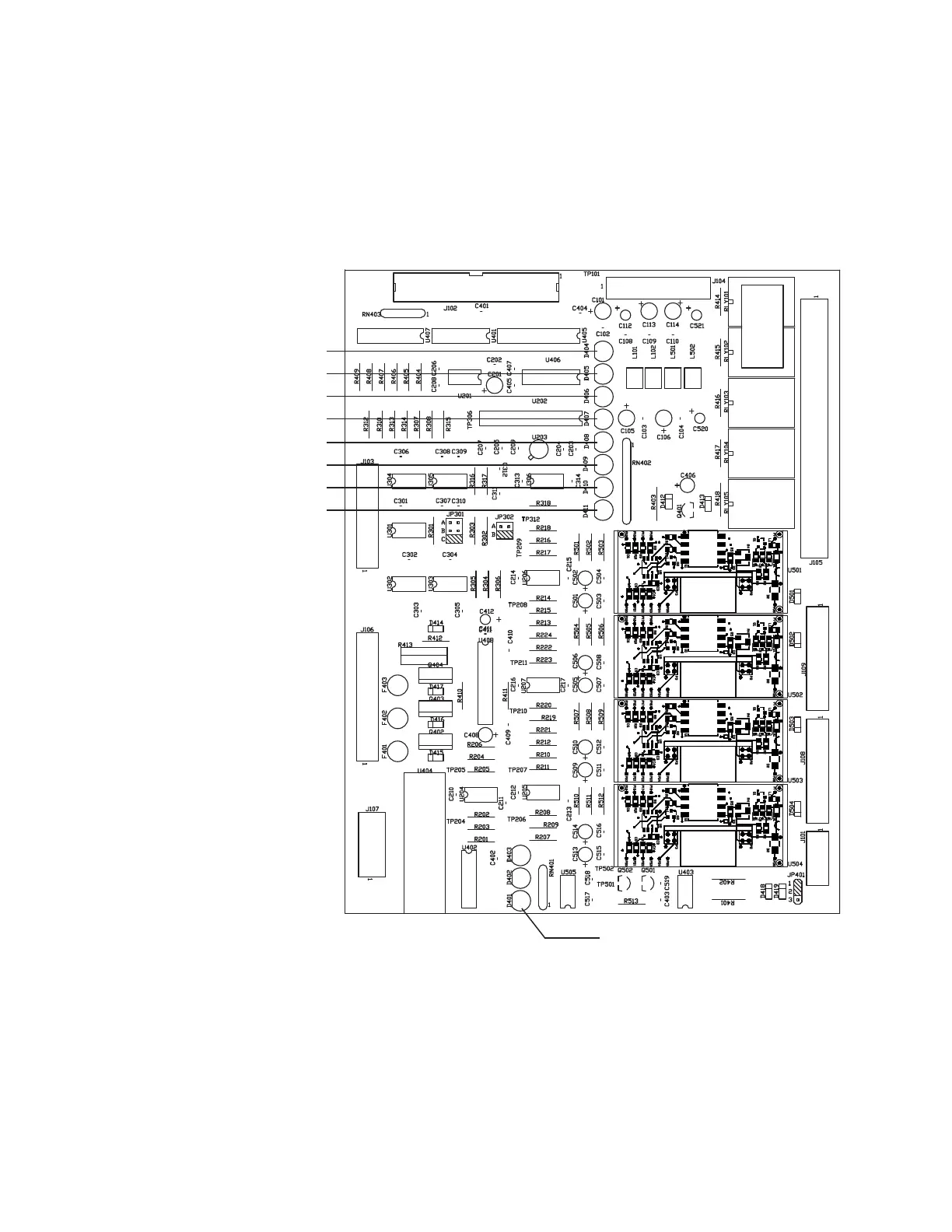
five minutes. Verify this by viewing the red LEDs D409 (Column A
Solenoid), D410 (Column B Solenoid), and D411 (Zero Solenoid)
on the Customer I/O board. These LEDs should be OFF.
c. The Column Block heater will be turned on to heat up the Col-
umn Block. Verify this by viewing the red LED D401 on the Cus-
tomer I/O board. It should be ON steady or pulsing.
Figure 3-10.
Customer I/O board
(P/N 100-1758).
LED D404 (Fault Relay)
LED D405 (Warning Relay)
LED D406 (Alarm Invalid/Zero-CAL Relay)
LED D407 (Concentration Alarm1)
LED D408 (Concentration Alarm2)
LED D409 (Column A Solenoid)
LED D410 (Column B Solenoid)
LED D411 (Zero Solenoid)
D401 (Column Block Heater)
 Loading...


