Installation and Start-Up | 3-39
5. While observing the Sample Gas Pressure Gauge on the analyzer
backpan, use the Sample Gas Pressure Regulator to increase the Zero
gas pressure to 550 KPA (80 PSIG).
6. Shut off the Zero gas flow at the cylinder and wait approximately two
minutes to allow the pressure in the sample system to stabilize. If the
reading on the pressure gauge starts to decrease, use a leak detection
fluid (such as Snoop
®
) on the sample system to find the problem area.
7. Repeat Steps 4 through 6, but select ‘2’ (column-B flow) in Step 4.
8. From the Vent Outlet, bleed down the sample system to atmospheric
pressure (check gauge).
To avoid tearing the Membrane Filters in the Filterblock, always bleed
down the sample system pressure on the downstream (outlet) side of
the Filterblock. Pressure differentials of more than 210 KPA (30 PSI)
from the inlet side to the outlet side can tear the Filters and they will
have to be replaced.
Close the valve on the Vent Line (or remove the Vent Line and cap the
Vent Outlet).
If the Sample Line is connected to the analyzer, disconnect it from the
Sample Inlet fitting and connect Zero gas to the Sample Inlet fitting.
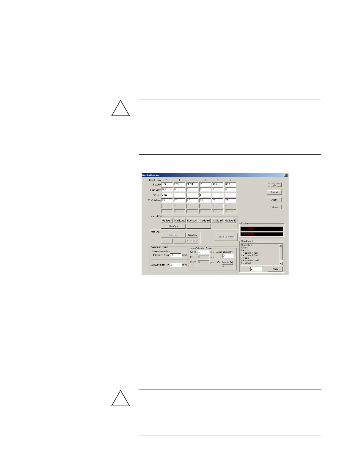
4. From the Gas Calibration dialog box, change the Flow Control setting
to ‘1’ (column-A flow). Click OK then Apply. Do not save the changes
to EEPROM.
To avoid damaging the pressure transducer, do not set the pres-
sure higher than the pressure transducer rating, either 0–210 kPaa,
(0–30 psia), 0–700 kPaa (0–100 psia), or 1380 kPag (200 psia) for
the 0–3450 kPaa (0–500 psia) transducer. 1380 kPag (200 psia) is the
maximum Cell Pressure allowed for the analyzer certification. Refer
to system drawings for your system’s pressure transducer rating.
!
CAUTION
!
CAUTION
Figure 3-20.
Gas Calibration dialog
box.
 Loading...


