Page 79
EVACU ELITE
INSTALLATION, COMMISSIONING AND USER MANUAL
8 Connecting to the EvacU
ELITE
8.1 General
The mains termination is to the mains isolator located in the top left hand of the cabinet.
All other terminations are accommodated to the front of the cards mounted in the universal racks.
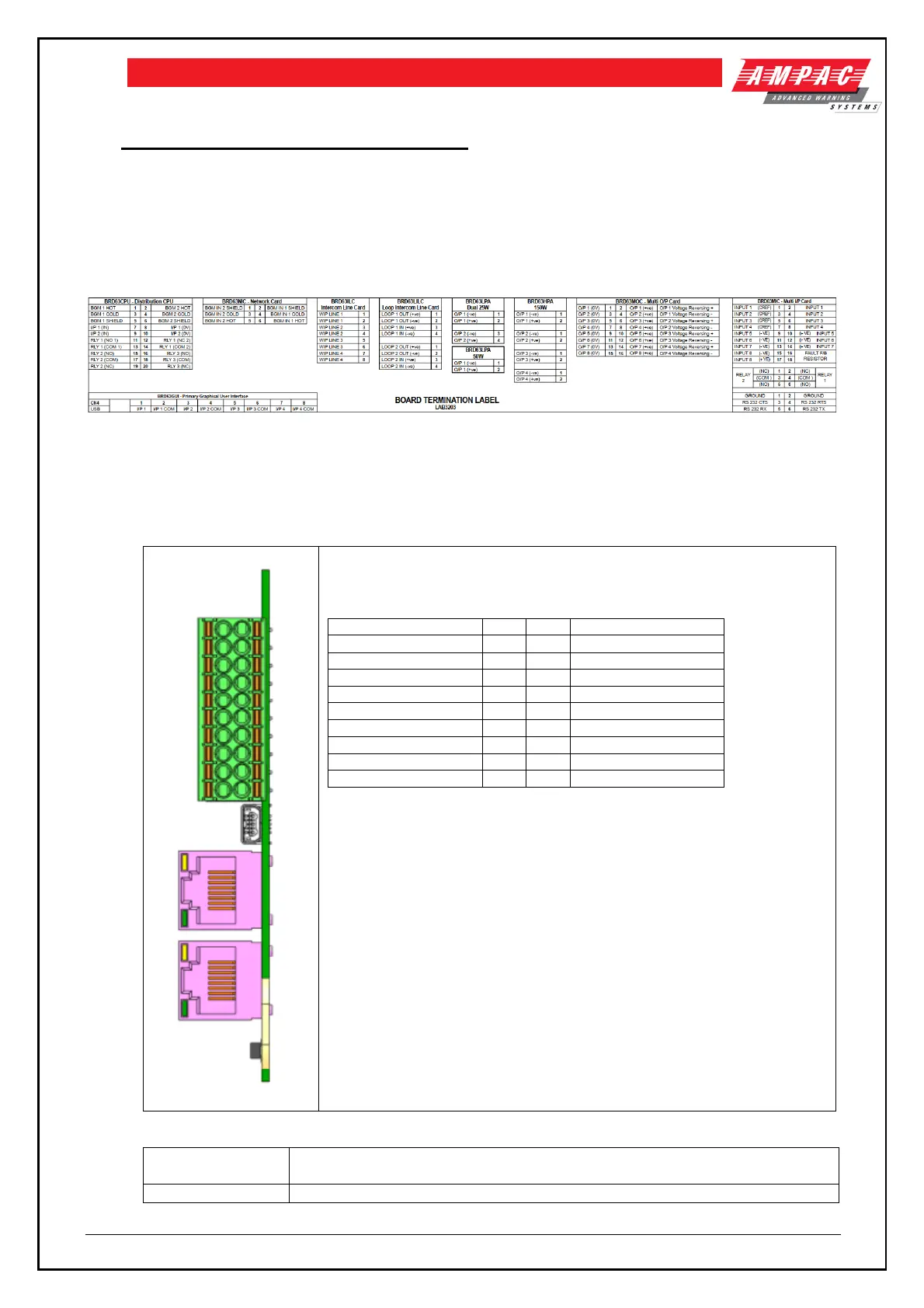
The following label is located on the inner door and details terminations for all cards.
Figure 8-1 Label 3203 detailing terminations for each card type
8.2 Distribution CPU
8.2.1 Connections
Following table details the field connections to the distribution CPU
Mini USB Connector
RJ45 1 provides the network connection to the GUI
RJ45-2 Redundant connection to the GUI
Analog line level audio input (hot, cold and shield), 10kΩ impedance, max
input +4dBu
Supervised input, selectable EOL, common reference.
 Loading...