Page 88
EVACU ELITE
INSTALLATION, COMMISSIONING AND USER MANUAL
The following table details audio load, wire size and length of cable runs.
Calculations are based on a 1 dB of loss (approx. 10V attenuation at the end of the cable run)
Max capacitance must be below 75nF and max inductance must be below 1mH
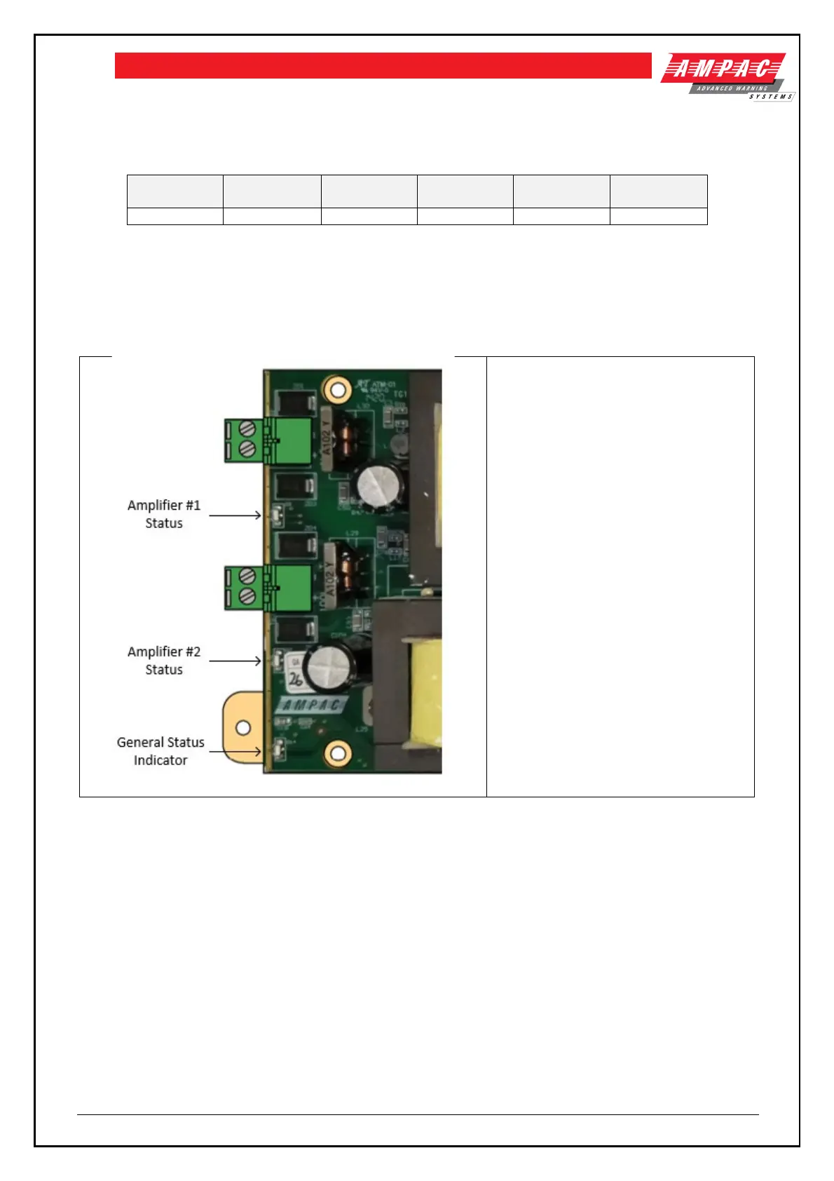
8.5.2 Indicators
The Dual 25Watt amplifier card has one status indicator per amplifier output (2) and a general status indicator.
See below
Amplifier Status Indicators
Dual indicators
RED: Output is activated (should be red
all the tone – showing the test tone is
being broadcast)
FLASHING AMBER – Fault condition –
short circuit / open circuit.
General Status Indicator
OFF: cards have no power or processor
is fault
FLASHING GREEN: board is operating,
no faults
FLASHING AMBER: board has a fault
condition
STEADY AMBER: Not receiving
commands from the Distribution CPU
8.5.3 Field wiring
 Loading...