Page 85
EVACU ELITE
INSTALLATION, COMMISSIONING AND USER MANUAL
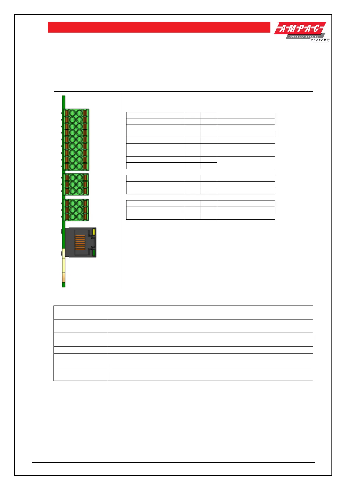
8.4 Multi-purpose interface card (MIC)
8.4.1 Connections
Following table details the field connections to the MIC
Interface to Ampac FireFinder
PLUS
Add On bus
Single ended inputs, common floating reference with selectable EOL
Differential inputs, individual floating reference with selectable EOL
Differential input, with floating reference with fault feedback (user selectable
resistance)
Single pole, double throw (COM, NO, NC)
RS232C serial port, with CTS and RTS available. Currently unused
Add On bus connection to the Ampac FireFinder
PLUS
Inputs 1 thru 8 are typically used as alarm inputs. Input 8 has a user selectable fault feedback resistor.
Relays 1 and 2 are general purpose
The RJ45 connector is dedicated as the HLI to the FireFinder
PLUS
8.4.2 Indications
The Multi-purpose interface card has one status indicator, located adjacent to the Ampac FireFinder
PLUS
Add
On bus connector
 Loading...