5-10 Keypad Membrane and Main Keypad PCB Replacement Chapter 5 — Assembly Replacement
5-14 PN: 10580-00342 Rev. D MS2720T MM
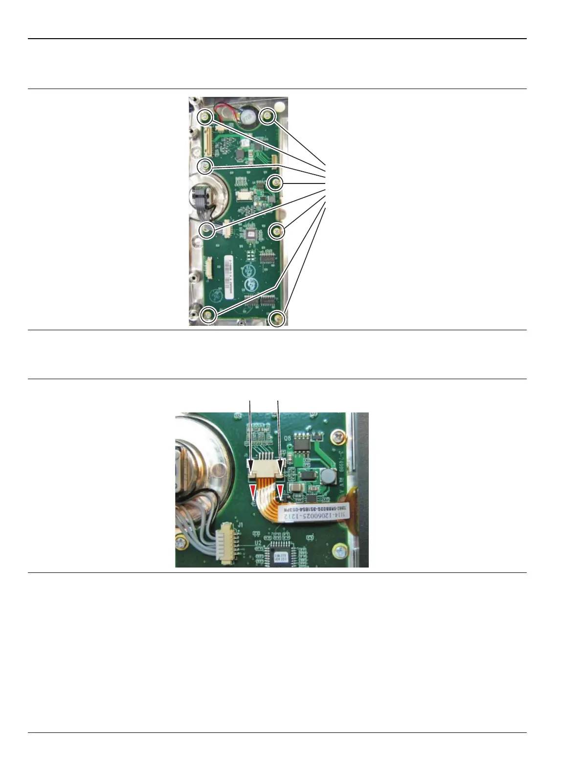
5. Remove the 8 screws securing the Keypad PCB to the front panel and carefully lift it out. The rubber
Keypad Membrane is located under the Keypad PCB (Figure 5-12).
6. Reverse the above steps to install the replacement assembly, with the following cautions:
• Carefully close the locking tab on connector J5 to secure the flexible Touch Screen connection.
The tab should “snap” into position when fully closed.
• The Keypad PCB stores the touch screen calibration data. If the Keypad PCB is replaced, then a
touch screen calibration must be performed. If no touch screen calibration data is stored in the new
Keypad PCB when powering on an instrument, it will stay at the boot up screen with the Anritsu
logo shown and a message at the bottom of the screen stating: “Failed to load touch screen
calibration data. Please re boot the instrument.” If this message is displayed, power off the
instrument and simultaneously holding down the Shift-4-0 keys while pressing the power on
button. Now the instrument will boot up in bootstrap mode and prompt you to perform a
touch-screen calibration. After following the on-screen calibration directions, power the
instrument off and it will boot up correctly on the next power on cycle.
Figure 5-12. Keypad PCB
Figure 5-13. Keypad Touch Screen Connector
Remove 8 screws
to remove Keypad
PCB
Pull tabs down to remove Touch Screen cable
 Loading...


