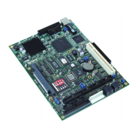
SBC-GX1 Technical Manual Detailed hardware description
9-bit TFT Panel data bus bit 18-bit TFT 12-bit TFT
640x480 1024x768
FPD 5 B5 B5 B5 B5
FPD 4 B4 B4 B4 B4
FPD 3 B3 B3 B3 B3
Even
FPD 2 B2 B2 B2
FPD 1 B1 B1
FPD0 B0 B0
Odd
The flat panel and CRT interface signals are routed to two separate connectors, both
displays can be driven simultaneously. The ability to drive both displays is dependant on
the particular timing parameters of the flat panel display. It is not always possible to
select appropriate clock rates to achieve an output on the CRT and flat panel displays.
The CRT output signals are routed to a 16-way 0.1” boxed header PL11. These signals
will normally be connected directly to a VGA compatible CRT monitor. A suitable cable
is provided as part of the SBC-GX1 development kit. The following table shows the
connection details for this cable. The CRT signals may be affected by noise and
therefore this cable should be kept as short as possible and should be routed away
from other signals to stop any crosstalk.
PL21 Pin Signal Name 15 way D-Type High Density
1 RED 1
2 Ground 6
3 GREEN 2
4 No Connection 4
5 BLUE 3
6 Ground 7
7 No Connection 9
8 No Connection 11
9 Ground 8
10 Ground 5
11 Ground 10
12 HSYNC 13
13 No Connection 12
14 VSYNC 14
15 No Connection 15
16 No Connection -
© 2004 Arcom Issue D 69

 Loading...