SBC-GX1 Technical Manual Detailed hardware description
General purpose I/O
Eight general purpose I/O lines are provided on the SBC-GX1. These lines are routed
to a 20-way 0.1” header PL13. The header provides un-buffered and buffered versions
of the lines. The buffered version can be used to drive higher output current (up to
24mA per output) than the un-buffered version.
The I/O lines are connected to GPIO line from the National Semiconductor NS97317
Super I/O controller. The table below shows the relationship between the GPIO lines on
the super I/O device and the I/O lines on PL13
NS97317 GPIO Line PL13 GPIO Line
GPIO20 I/O0
GPIO21 I/O1
GPIO23 I/O2
GPIO24 I/O3
GPIO16 I/O4
GPIO37 I/O5
GPIO12 I/O6
GPIO17 I/O7
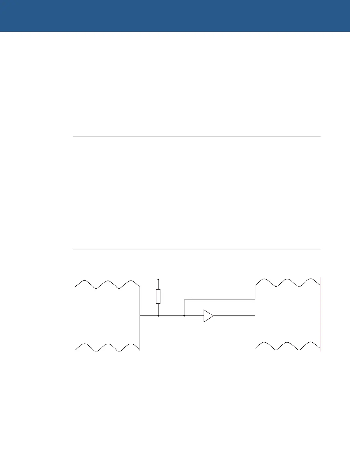
The following diagram shows the configuration of each I/O line:
+5V
10k
I/O
Buffered I/O
NS97317
GPIO line
PL3
1/8 74HCT244
The NS97317 GPIO lines must be configured using the registers built into the device to
ensure they function correctly. Various features can be programmed for each pin,
including direction control and pull up/down resistors. As the GPIO lines also share pins
with dedicated functions these must be disabled if the line is to be used.
The support CD contains some example ‘C’ source code that can be used to configure
the signals. This can be found in the ARCOM Examples directory.
© 2004 Arcom Issue D 76

 Loading...
