SBC-GX1 Technical Manual Detailed hardware description
User jumpers
There are two user jumpers on the SBC-GX1 - LK11 and LK12. The status of these
user jumpers can be read via I/O address 259H bits 1 and 2 respectively. If the link is
made then the corresponding bit is read as a logic ‘0’. (See the
Jumpers and
connectors
section, page 18, for further details.) These jumpers do not have any
defined function on the board, and so can be used to select options in your application
program.
USB interface
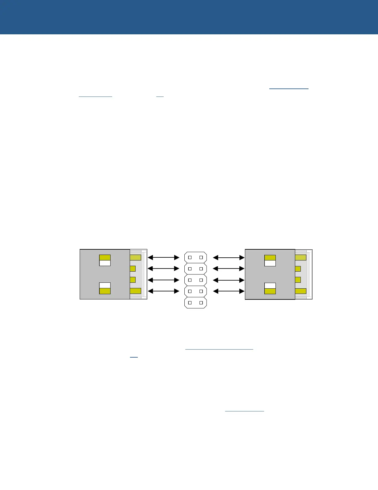
There are two Universal Serial Bus (USB) interfaces on the SBC-GX1. These interfaces
have been designed to support the Open Host Controller Interface (OpenHCI).
There are four signal lines associated with each USB channel:
• VBUS
• DATA-
• DATA+
• GND
Their arrangement is summarized in the following illustration:
A USB power control switch is used to control the power and protect against short
circuit conditions. This can be enabled/disabled by the processor and the USB function
needs to be enabled in the BIOS to ensure that power is supplied to each device. The
USB feature is controlled using the
Chipset features setup screen within the Setup
utility - see page 34
for details.
If the USB voltage is short circuited or more than 500mA is drawn from either supply the
switch turn offs the power supply and automatically protects the device and board. The
VBUS signal is derived from the +5V supply via the SBC-GX1.
If you are looking for details about the USB bus, or would like to determine whether
particular peripherals are available, please go to
www.usb.org.
1
2
3
4
1
2
3
4
PL 7
USB Connector 1
USB Connector 2
1
2
10 (GND)
(GND) 9
VBUS 1
DNEG 1
D POS 1
GND
VBUS 2
DNEG 2
DPOS 2
8
DAT
- DAT
-
GND
DATA+ DATA+
© 2004 Arcom Issue D 75

 Loading...
