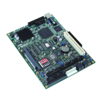
SBC-GX1 Technical Manual Detailed hardware description
IDE interface
The SBC-GX1 has a two Integrated Drive Electronics (IDE) controller interfaces. These
IDE controllers are 32-bit PCI device and support Ultra DMA/33 modes of operation.
The IDE controllers also support Bus mastering mode and a suitable driver is supplied
on the support CD. The 32-bit interface provides a much faster access speed than the
original ISA style interface.
Primary interface
This interface supports up to two hard disk drives. The disk drives are connected via a
1:1 40-way ribbon cable using PL2. One drive must be configured as a ‘master’ and the
other drive as a ‘slave’. An IDE compatible CD-ROM drive can also be used and should
be configured as the ‘slave’ device.
The BIOS automatically detects which devices are connected via this interface and
configures the controller accordingly. The BIOS can be configured to make either the
hard disk drive or CD-ROM the default boot device.
If a hard disk drive is attached to this interface, with the default configuration the drive is
used as the standard boot device and the flash disk, if present, becomes the next
available drive.
Secondary interface (CompactFlash)
The secondary controller is used to support a compact flash card interface. The
CompactFlash socket PL25 is mounted on the underside of the SBC-GX1. This socket
can be used to support both Type I and Type II CompactFlash cards. The
CompactFlash card can be used to replace a mechanical drive in the system. If a
formatted bootable card is placed in this socket, and there is no boot device connected
to the primary controller, the BIOS boots from CompactFlash.
Floppy disk controller
The floppy disk interface is designed to support up to two standard floppy disk drives.
Connections are made via a 34 way 0.1” boxed header PL17. (See
Appendix B –
Connector details
for pin assignment details.) All standard capacities including 360KB,
720KB, 1.2MB,1.44MB and 2.88MB are supported. The BIOS must be configured
appropriately for the desired format using the Setup utility. The default BIOS
configuration supports a single 1.44MB floppy disk drive configured as drive A: and if
this drive contains a bootable floppy when the board is powered up it is used as the
default boot device. If no drive is present the BIOS continues to operate correctly.
The floppy disk drive cable should have three connectors, two of which are connected
directly 1:1 and one of which has pins 10-16 twisted. If only one drive is required it
should be connected via the twisted cable and the drive should be setup to use drive
select 1. If two drives are required the second drive should also be configured for drive
1, but should be connected via the straight connector. This connection does not provide
power and therefore a separate cable from the main supply should be used.
The floppy disk interface is decoded in I/O address space at 3F0-3F7H and uses IRQ6
and DMA channel 2.
© 2004 Arcom Issue D 72

 Loading...