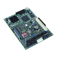
SBC-GX1 Technical Manual Detailed hardware description
Power supply
The SBC-GX1 is designed to operate from a single +5V ± 5% (4.75V to +5.25V) supply.
The power connector PL12 has two +5V connection and three ground connections.
These connections are connected on board. PL12 also has a +12V connection defined.
This supply is not required for the SBC-GX1 under normal operation, but may be used
to supply +12V to the PC/104 stack if required.
Two other supply voltages are present on the board: +2.0V and +3.3V. These supplies
are required for the CPU core and on-board devices. The +3.3V supply is routed to the
PCI header to enable it to be used by additional cards, and can be used to power +3.3V
flat panels via PL15.
The +5V supply is monitored automatically on-board. If this supply falls below 4.63V,
the board is placed in ‘reset’. When the power supply rises above this threshold voltage
the board starts to operate again. This power supply monitor ensures that the board
does not hang if the supply voltage fails at any point.
The BIOS has built-in power management, which can be enabled using the Power
management screen within the Setup utility – see page 36
. Various aspects of the board
can be controlled by the power management software. The board can be placed in a
power-down state, and normal operation can be resumed using an external input from
the mouse, keyboard, serial ports, real time clock, etc. The power management
software is designed to monitor activity and starts to slow down the CPU and switch off
functions if long periods of inactivity are detected.
The SBC-GX1 has a dedicated I/O register that can be used to power down the RS232
serial buffers if they are not required. Each buffer has an individual control line, so they
can be switched on and off in any combination. The default configuration for these
buffers at power on is to be enabled. This ensures that the board operates correctly
when first powered. Once running the buffers can be disabled during periods of
inactivity.
The register is located at I/O address 260H and the bit definitions are shown in the
following table:
Bit Description Operation
0 Shutdown COM1
1 Shutdown COM2
2 Shutdown COM3
3 Shutdown COM4
0 = Enabled (Default)
1 = Disabled
4 No Function
5 No Function
6 No Function
7 No Function
© 2004 Arcom Issue D 80

 Loading...