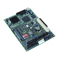
SBC-GX1 Technical Manual Detailed hardware description
current when switched on therefore the anode of each device should be connected to
PL3 pin 1 and the cathode to the appropriate status line.
The support CD contains drivers for most operating systems and network software.
These are stored in the Ethernet directory.
16-bit SoundBlaster
The audio support provided by the SBC-GX1 is fully compatible with the 16-bit
SoundBlaster interface. This device provides support for stereo line in and line out and
mono Microphone input. The SoundBlaster is supported via the XpressAudio software
which is built into the BIOS code.
A National Semiconductor LM4548 AC97 Audio codec provides the output and mix
signals from the input sources. The codec can be used to set the output level of each
source and provide a composite signal. There is no amplifier on-board, so either active
speakers or an amplifier module must be connected to the output.
Connection is made via a 10-way 0.1” header PL24. (See
Appendix B – Connector
details
for pin assignment details.)
The audio device is connected to the PCI bus. To ensure backward compatibility it must
be setup to respond to standard Audio I/O address mapping, IRQ and DMA signals. The
BIOS can be configured to set the appropriate locations. The default settings are as
follows:
Audio I/O Base Address 220H
MPU-401 I/O Base Address 330H
Audio IRQ Select IRQ5
Audio Low DMA Select DMA 1
Audio High DMA Select DMA 5
These can be modified in the Integrated Peripherals screen within the Setup utility –
see page 39
for details.
Drivers are supplied on the support CD for Windows 98 and NT 4.0.
Watchdog timer
The SBC-GX1 contains a watchdog timer, which can be used to protect against
erroneous software. There are two timeout periods available - either 2 or 8 seconds
depending on the position of LK2. The watchdog timer is disabled by a reset, and can
be started by performing an I/O write to location 93H (any value causes the timer to
start). If another I/O write to this location is not performed within the timeout period the
board will be RESET. Writes must be continually performed to enable the board to
function correctly - there is no software disable mechanism once the timer is started.
The watchdog timer can be disabled permanently by removing user link LK1. This
feature may be useful during debug/development.
© 2004 Arcom Issue D 74

 Loading...