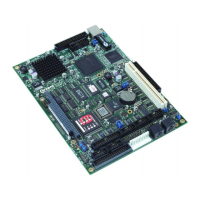
SBC-GX1 Technical Manual Detailed hardware description
RS422
The RS422 interface provides full duplex communication. The signals available are
TXA, TXB, RXA, RXB and Ground. The maximum cable length for an RS422 system is
4000ft and it supports 1 transmitter and up to 10 receivers. To enable RS422 operation
LK8 should be removed and the RTS line from COM4 should be at logic ‘0’. LK9 and
LK10 should be made if the board is at the end of the network.
RS485
This is a half-duplex interface that provides combined TX and RX signals. PL14 pin 5
provides TXB/RXB and pin 6 provides TXA/RXA. A ground connection is also required
for this interface. The maximum cable length for this interface is the same as
RS422(4000ft), but RS485 supports up to 32 transmitters and receivers on a single
network. Only one transmitter should be switched on at a time. The SBC-GX1 uses the
RTS signal to control transmission, when this signal is at logic ‘1’ the driver is switched
off and data can be received from other devices. When the RTS line is at logic ‘0’ the
driver is on. Any data that is transmitted from the SBC-GX1 will automatically be echoed
back to the receiver. This enables the serial communications software to detect that all
data has been sent and disable the transmitter when required. LK8 should be made to
enable the RS485 interface. LK9 and LK10 should be made if the SBC-GX1 is at the
end of the network.
Parallel port
The parallel port is fully IEEE1284 compatible and provides Standard Parallel Port
(SPP), Enhanced Parallel Port (EPP) and Extended Capabilities (ECP) support. The
parallel port is decoded at I/O address location 378-37FH (LTP1) and uses IRQ7. In
ECP mode the BIOS can be used to select an appropriate DMA channel; the default
channel is DMA 3.
The parallel port has built-in protection circuitry to protect against powered devices
being connected when the main supply is removed and damaging the device. Each
data and control signal is designed to source/sink 14mA maximum.
The parallel port connector PL16 is a 26-way 0.1” boxed header. The pin assignment of
this connector has been designed to provide 1:1 connection to an IDC 25-way D-Type
socket. (See
Appendix B – Connector details for pin assignment details.) The socket is
compatible with a standard PC parallel port connector.
The parallel port can be used to connect an external printer, tape drive, disk drive,
scanner etc., or can be used to provide additional digital I/O capability.
© 2004 Arcom Issue D 79

 Loading...