2.10 Ethernet interface
The MPS2 and MPS2+ FPGA Prototyping Boards provide an Ethernet MAC interface.
Overview of the Ethernet interface.
The Ethernet interface consists of a 16-bit interface on the FPGA, a combined Ethernet MAC and PHY
on the board, and Ethernet connector for external connection.
Note
The MAC/PHY connects to the same 16-bit interface as the 16MB PSRAM external memory.
The MPS2 and MPS2+ FPGA Prototyping Boards contain three LEDs that denote Ethernet activity:
• LINK LED:
— On denotes Ethernet connection is established.
— Off denotes Ethernet connection is not established.
• DPLX LED:
— On denotes connection operating in duplex mode.
— Off denotes Ethernet connection operating in simplex mode.
• 100Mbs LED:
— On denotes Ethernet connection operating at 100Mbs.
— Off denotes Ethernet connection operating at 10Mbs.
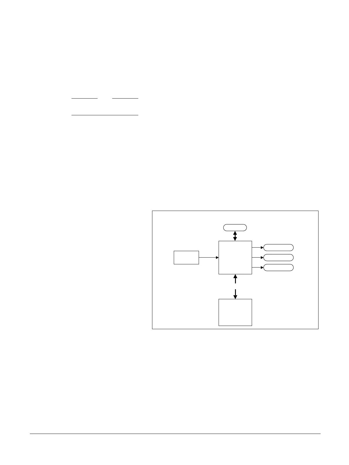
The following diagram shows the Ethernet interface.
Ethernet
MPS2/MPS2+ FPGA Prototyping Board
FPGA
MAC/PHY
25MHz
CLK
16-bit
DPLX
LINK
100Mbs
Ethernet activity LEDs
Figure 2-10 Ethernet interface
Related information
5.9 Ethernet connector on page 5-88
2.12 External user memory on page 2-36
2 Hardware Description
2.10 Ethernet interface
100112_0200_09_en Copyright © 2013–2016, 2018–2020 Arm Limited or its affiliates. All
rights reserved.
2-34
Non-Confidential