5.5 UART connector
The MPS2 and MPS2+ FPGA Prototyping Boards provide one general‑purpose female UART connector
that supports access to the FPGA.
The general‑purpose UART connector connects through a level-shifter to the FPGA. The meaning of the
UART signals depends on the design which you implement in the FPGA.
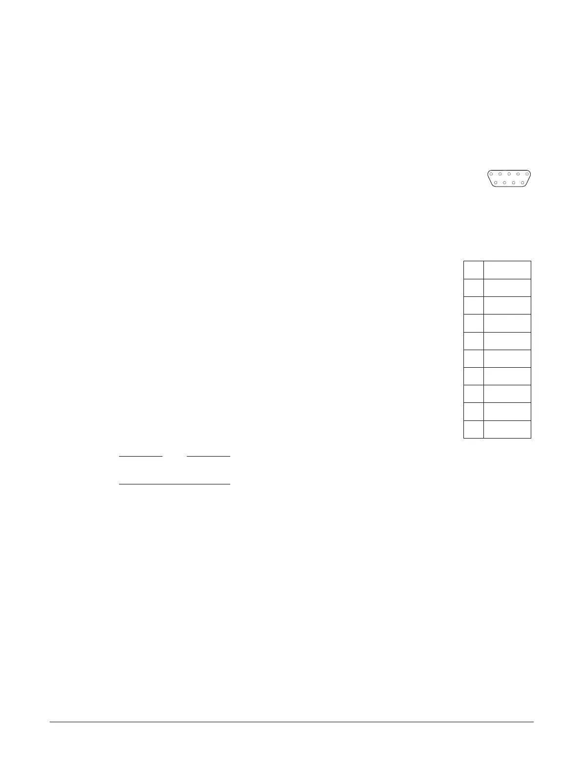
The following figure shows the general‑purpose UART connector.
1 2
6 7 8 9
3 4 5
Figure 5-9 General-purpose female UART connector
The following table shows the pin mapping for the general‑purpose UART connector J20.
Table 5-10 General-purpose UART connector, J20, signal list
Pin Signal
1 NC
2 SER_RX
3 SER_TX
4 NC
5 SER_GND
6 NC
7 SER_RTS
8 SER_CTS
9 NC
Note
SER_RTS loops back to connect to SER_CTS.
Related information
2.7 UART interface on page 2-31
1.3 Location of components on the MPS2 FPGA Prototyping Board on page 1-17
1.4 Location of components on the MPS2+ FPGA Prototyping Board on page 1-19
5 Signal Descriptions
5.5 UART connector
100112_0200_09_en Copyright © 2013–2016, 2018–2020 Arm Limited or its affiliates. All
rights reserved.
5-84
Non-Confidential