3.3 Configuration system
The MPS2 and MPS2+ FPGA Prototyping Boards provide hardware infrastructure to enable board
configuration during powerup or reset.
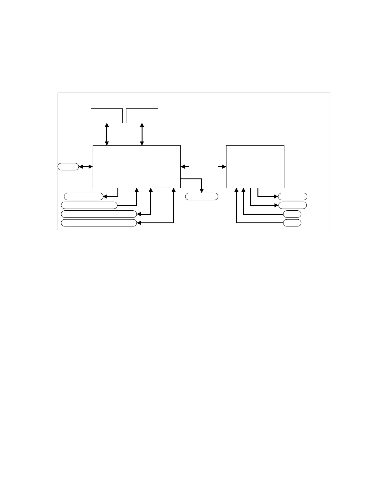
The following diagram shows the board configuration system.
microSD card
(USBMSD)
Configuration
EEPROM
User DIP switches 1-8
FPGAMCC
USB 2.0
Configuration
MPS2/MPS2+ FPGA Prototyping Board
ON/OFF/Soft RESET push button
Hardware RESET push button
User LEDs 1-8
PB0
USERLED0
PB1
USERLED1
DONE LED
Figure 3-1 Configuration system
Configuration port connected to an external workstation
If you connect an external workstation to the MCC USB 2.0 Full Speed port, you can access the
configuration memory in the microSD card. You can then edit and copy configuration files and software
images to the SD card.
Related information
2.5 USB 2.0 Full Speed interface on page 2-29
3.6.2 config.txt generic board configuration file on page 3-57
3.6.3 Contents of the MB directory on page 3-57
3.6.4 Contents of the SOFTWARE directory on page 3-58
3.6.1 Overview of configuration files and microSD card directory structure on page 3-56
3 Configuration
3.3 Configuration system
100112_0200_09_en Copyright © 2013–2016, 2018–2020 Arm Limited or its affiliates. All
rights reserved.
3-52
Non-Confidential