5.8 Audio connectors
The MPS2 and MPS2+ FPGA Prototyping Boards each provide two 3.5mm stereo jack connectors that
connect to a low-power stereo audio codec. The two connectors provide an independent line-level stereo
input and an independent line-level stereo output.
The audio codec connects to general‑purpose pins on the FPGA. The availability of an audio controller
depends on the design which you implement in the FPGA.
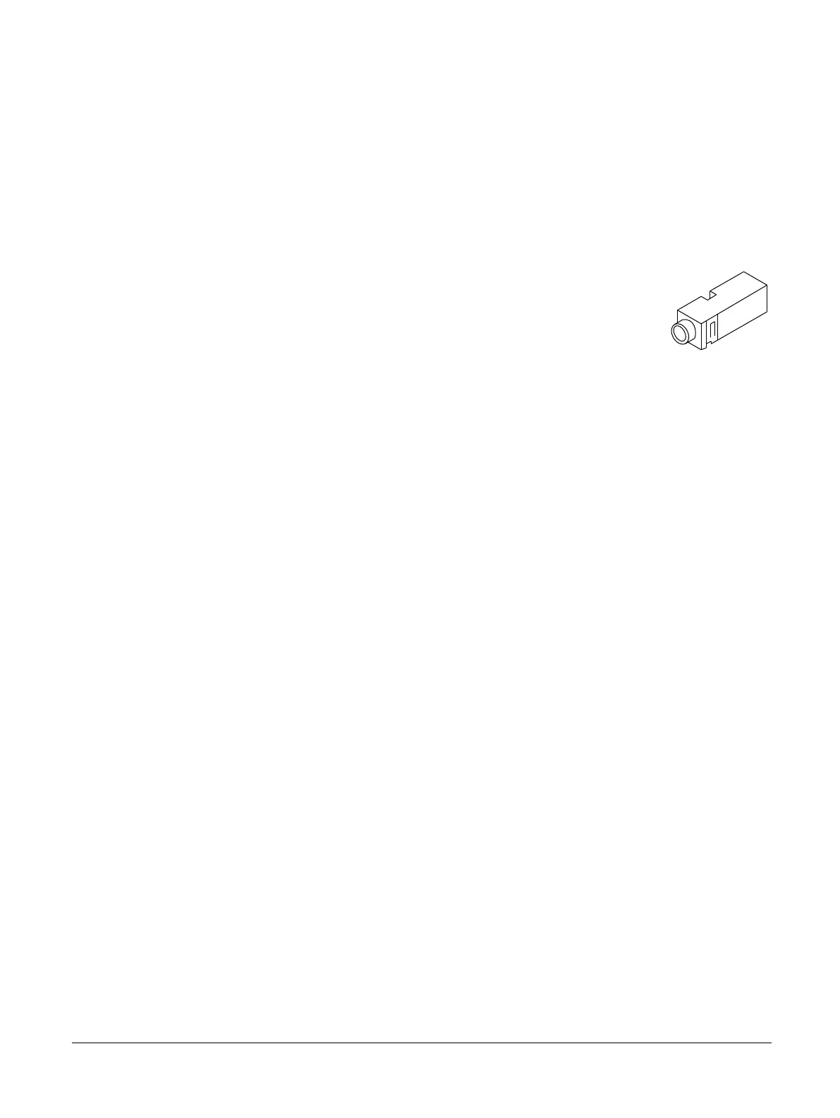
The following figure shows the audio connector. Audio In is component number J32 and Audio Out is
component number J33 on the board.
Figure 5-12 Audio connector
Related information
2.9 Audio interface on page 2-33
1.3 Location of components on the MPS2 FPGA Prototyping Board on page 1-17
1.4 Location of components on the MPS2+ FPGA Prototyping Board on page 1-19
5 Signal Descriptions
5.8 Audio connectors
100112_0200_09_en Copyright © 2013–2016, 2018–2020 Arm Limited or its affiliates. All
rights reserved.
5-87
Non-Confidential