A.1 Electrical specification
This electrical specification provides information on the current characteristics of the MPS2 and MPS2+
FPGA Prototyping Boards. It also enables you to implement your FPGA design without exceeding the
power and current ratings of the board and the temperature rating of the FPGA.
This section contains the following subsection:
• A.1.1 FPGA current requirements on page Appx-A-91.
A.1.1 FPGA current requirements
You can calculate current requirements for your MPS2 or MPS2+ FPGA Prototyping Board FPGA
image.
See http://altera.com for software to help you calculate the current requirements for your particular
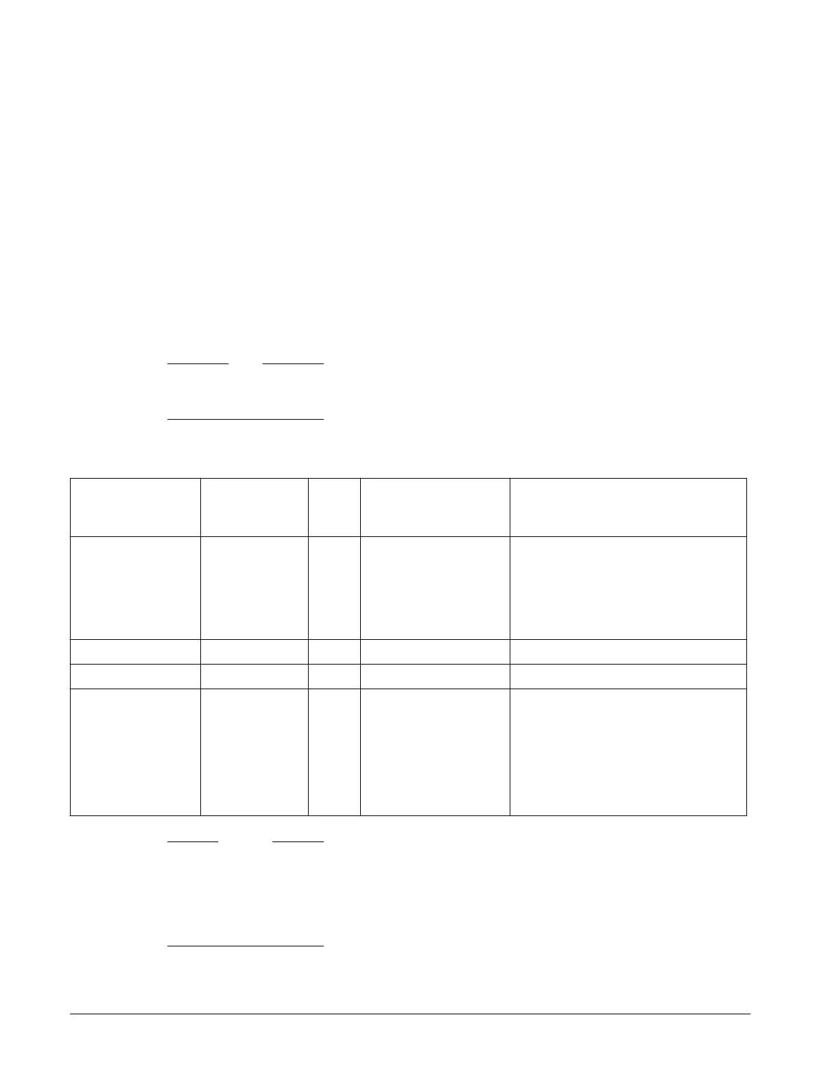
application. The following table shows the power available for each power domain, or group of power
domains, of the FPGA.
Note
This table applies to both the Altera Cyclone 5CEA7 FPGA on the MPS2 FPGA Prototyping Board and
to the Altera Cyclone 5CEA9 FPGA on the MPS2+ FPGA Prototyping Board.
Table A-1 Available FPGA current
FPGA power domain Board power
supply
Voltage Maximum available
current from board
power supply
Comment
VCCO_3V0
VCCPD_3V0
VCCPGM
VREF_3V
3V 3V 50mA -
VBATT VBAT 3V - -
VCC 1V1 1V1 2.5A -
VCCAUX
VCCO_2V5
VCCPD_2V5
VREF_2V5
VCCA_FPLL
2V5 2V5 1.5A An analog filter on the MPS2 and MPS2+
FPGA Prototyping Boards smooths the
supply to the VCCA_FPLL domain.
Caution
• Some FPGA designs might exceed the current and temperature rating of the board. Therefore you
must estimate the power requirements of such designs, using tools such as Quartus II before
implementation.
• The FPGA package has a thermal resistance of 13.7° per Watt. The recommended maximum FPGA
junction temperature is 85°C.
Related information
2.14 Power on page 2-42
A Specifications
A.1 Electrical specification
100112_0200_09_en Copyright © 2013–2016, 2018–2020 Arm Limited or its affiliates. All
rights reserved.
Appx-A-91
Non-Confidential