5.4 USB 2.0 connector
The MPS2 and MPS2+ FPGA Prototyping Boards provide one USB 2.0 mini-B connector that provides
a USB 2.0 Full Speed port. This port supports configuration file editing in the microSD, virtual UART
access to the FPGA, and CMSIS-DAP FPGA debug.
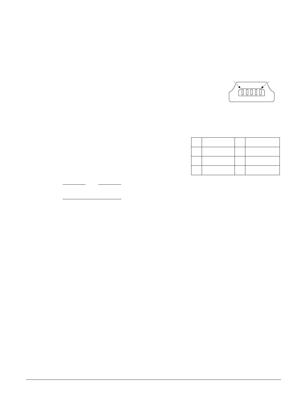
The following figure shows the USB 2.0 mini-B connector.
Pin 1
Pin 5
Figure 5-8 USB 2.0 mini-B connector
The following table shows the pin mapping for the USB 2.0 mini-B connector J14.
Table 5-9 USB 2.0 mini-B connector, J14, signal list
Pin Signal Pin Signal
1 MSD5V 2 MSD_DMRAW
3 MSD_DPRAW 4 MSD_ID
5 GND 6 GND_EARTH
Note
• The GND_EARTH connection is the casing of the mini-B connector.
Related information
2.5 USB 2.0 Full Speed interface on page 2-29
1.3 Location of components on the MPS2 FPGA Prototyping Board on page 1-17
1.4 Location of components on the MPS2+ FPGA Prototyping Board on page 1-19
3.2 Remote USB operation on page 3-51
5 Signal Descriptions
5.4 USB 2.0 connector
100112_0200_09_en Copyright © 2013–2016, 2018–2020 Arm Limited or its affiliates. All
rights reserved.
5-83
Non-Confidential