Chapter One
1 - 8
Introducing Froment Load Banks
1 - 9
Non-unity Power Factor Testing
It is unusual for a generator to be presented with a purely resistive load. In real-world
applications it is much more likely that the load is made up of a combination of resistive,
inductive and capacitive elements (electric motors, lamp ballasts, etc.) which may be
continuously changing as various items of equipment are switched on and o.
The inductive and capacitive (reactive) parts of the load tend to store and then return
energy, and some proportion of the power supplied to the circuit is returned to the
generator. Consequently, more current has to flow to provide the required amount of
power to the circuit and the circuit is said to have a low (or non-unity) power factor. For
instance, to get 1kW of real power, a load with a power factor of 0.8 will require 1.25 kVA
apparent power to be supplied.
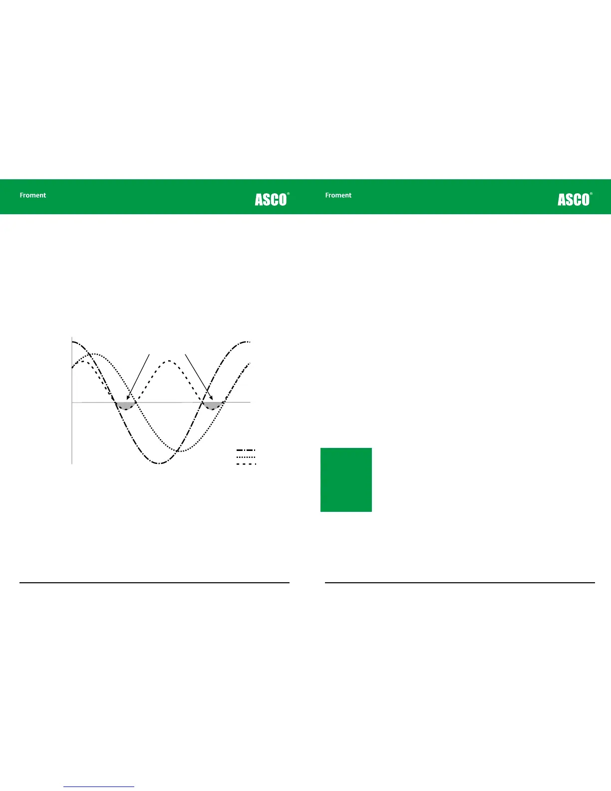
Figure 1-7 Typical power curve for power factor of 0.8
A low power factor puts additional stresses on alternators, voltage regulators, and switch
gear without necessarily putting additional load on the engine. Many generating sets are
designed to reach their maximum output when connected to a non-unity power factor
load.
To provide a realistic test, it is necessary for the load bank to simulate this situation. To
achieve this, the load bank elements need to consist of a mixture of resistive heating
elements and inductors. In some applications, capacitors are also used.
Voltage
Current
Power
0
Proportion of power
returned to the source
When is non unity power factor testing required?
This depends on the type of test that is required.
Sometimes, for smaller generators where a standardised alternator design is in use, the
electrical performance of the alternator and control gear can be assumed to be adequate.
In this case the only requirement during testing is to prove that the motive source of
the generating set is capable of operating at full power without overheating and a purely
resistive load is all that is required. This is sometimes referred to as active load (power
factor 1.0) or unity power factor.
However, in many situations the electrical performance of a generating set is of critical
importance. In these cases it is necessary to put the motive source, alternator and its
associated control gear all under stress during testing. To do this a combined load made
up of resistive and reactive elements is required.
Combined loads are also required to set up systems where multiple generating sets are
running in parallel or where it is necessary to simulate the start up of a large motor.
Multiple generator testing
Multiple generating sets running in parallel can present a problem for installers when it
comes to setting up load sharing and voltage regulation on a new system. A purely resistive
load will not provide the required load characteristics and a combined load is required for
initial calibration and testing.
What equipment is required?
Combined load testing can be accomplished by using a combined load bank (a load bank
consisting of a mixture of resistive and reactive load elements) or by running two or more
dierent type load banks in parallel.
The exact combination of equipment required will depend on the specific application.
Typically power factors from 1.0 to 0.7 are used but motor start simulation may require
a power factor as low as 0.4. See the appendices of this manual for more details of the
calculations involved.
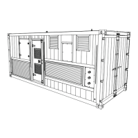
Note: Froment com-
bined, inductive and
capacitive load banks
are in the 6000 SERIES
range. Froment purely
resistive load banks
are in the 3000 SERIES
range and Froment con-
tainerised units are in
the 8000 SERIES range.