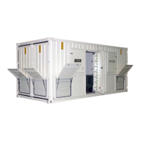
Load Bank Emergency Operation
If a Sigma 2 controller is unavailable it is possible to use the load bank ID rotary switch to
control the load bank.
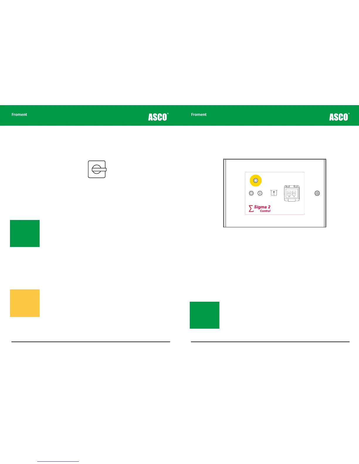
Figure 3-8 The load bank ID selector switch
Ensure that no Sigma Hand-held is plugged into the load bank and that the load bank is
powered up.
1. Press the Stop button.
2. Select <1> on the small rotary switch.
3. Press the Start button.
4. Select <6>. Wait for one second.
5. Select <0>.
When this control mode is enabled the local Start indicator will be illuminated and will blink
o at regular intervals.
6. Select <1> to <11> to apply proportionally more load.
Position <11> provides the maximum load available. The fan will start automatically when
required. If the load bank has inductive load element available load will be applied at a
power factor of 0.8.
7. Select <0> to reject all load.
The fan will stop after a time delay.
8. Press the Stop push button to disable Emergency Control Mode.
3 - 14
than one load bank, each
must have a different
1
2
3
4
5
9
7
8
10
11
0
LOAD BANK NUMBER
When controlling more
than one load bank, each
must have a different
1
2
3
4
5
9
7
8
10
11
0
Load Bank Operation
3 - 15
Chapter Three
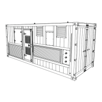
Load Bank Operation Using a Remote Station
The remote control station duplicates some of the controls on the main control panel and
provides sockets for connecting the Sigma 2 control cable to a suitable control interface.
Figure 3-9 Load bank remote station control panel
The remote station control panel is used in a similar way to the main control panel. However
the function of the main panel’s Stop/Reset button has been divided between two buttons
with an emergency stop facility.
The remote station control panel is usually fitted with the following controls:
Emergency Stop Button. Operating this causes the load bank to immediately shut down.
The fans, control circuits and load elements will be isolated but the Supply-on-Test may
remain live.
Reset Button. This is used to reset any error conditions (such as over-voltage or over-
temperature) that may have caused an automatic shutdown.
Start Button. Pressing this enables the load bank’s control system ready for
testing.
Sigma 2 Control Selector. This selects between the Sigma 2 connector on the remote
station and an additional connector at a satellite location (for example, in a secondary
control room).
OUT IN
load bank
remote station
CONTROL
SELECTOR
EMERGENCY
STOP
RESET START
Satellite
location
This remote
station
Note: Both the Start
and Reset buttons con-
tain indicator lamps that
duplicate the operation
of the main panel Stop
and Start indicators see
(page 3-9).
Note: To prevent
accidental operation of
this mode the timing
for this procedure must
be exact. If it does not
work the first time you
try it, try again.
Warning! These values
refer to the capacity
of the load bank - not
to the capacity of the
Supply-on-Test. Be
careful not to overload
the supply