4 - 6
The Hand-held Menu Display System
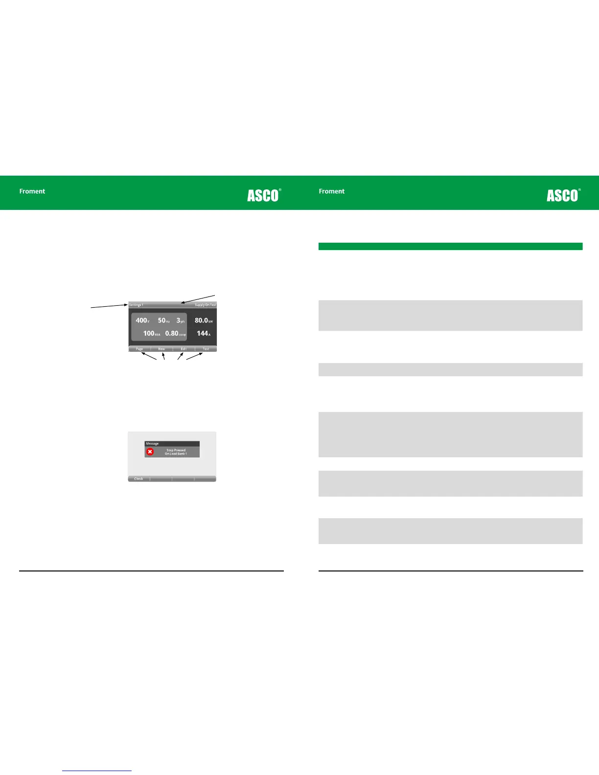
The Hand-held uses a menu display system for initial settings and also during the testing
process. The screen provides real-time instrumentation readings, status information and
labels for the four function keys (F1 to F4).
The screen shows details of the supply settings, built-in help and also provides access to
instrumentation to allow monitoring during testing.
Figure 4-3 The Hand-held screen display.
Sigma Status Messages
A message window is used to display status information and other messages from the load
banks.
Figure 4-4 Typical Sigma status message
Page Title
Function Key Labels
Status Bar
Hand-held Reference Guide
4 - 7
Error Message Description Possible Causes
Stop Pressed on Load Bank nn Load bank emergency stop signal is
present.
• Start button has not been pressed or was
pressed before the load bank had performed
its power on self-test (both Start and Stop
illuminated). Wait until the Stop button only is
illuminated before pressing the Start button.
• External Emergency Stop buttons (if fitted) are
depressed. Release all Emergency Stop button
and press the Start button.
• Load bank ESR not energising or faulty auxiliary
contact.
No Load Banks Active Check Cable No load banks are responding to the Hand-
held.
• If two, or more, load banks are connected -
check setting of station number switch. Each
load bank should be a unique number.
• Ensure each load bank Stop button is pressed
when station number changed.
• Faulty cable between Hand-held and load bank.
Fan Tripped On LoadBank nn Fan Overload signal not present when fan
run output energised.
• Fan Circuit Breaker or Overload Tripped. Check
fan is not obstructed and that it is free to rotate.
Then reset Trip or Circuit Breaker.
• Check motor current.
Fan Not Running On LoadBank nn Fan Contactor auxiliary contact signal not
present, when fan run output energised.
• Fan contactor not energising or faulty auxiliary
contact.
Fan Power Fault On LoadBank nn Fan/Control Circuit Power supply is outside
limits on voltage and/or frequency or a
phase is missing.
• Check control voltage, frequency and phases.
If the generator rating is incorrect run the load
bank from an auxiliary supply.
• Check the Fans and Controls Supply Selector
switch is in the correct position.
• Load bank fan supply VT fuses blown or VT’s
faulty. Check fuses and VT output.
Over Temperature On LoadBank nn Over Temperature signal not present.
• Load bank is over temperature. Ensure that the
load bank ambient temperature is not exceeded
and check hot air discharge is not recirculating.
Allow the load bank to cool, and then press Stop
and Start buttons.
• Over temperature trip faulty. More than one
over temperature trip may be fitted. These
devices will automatically reset when they cool
down.
Air Flow Failure On LoadBank nn Air Flow signal not present after fan output
energised.
• Fan or Duct obstructed. Flow detector faulty.
Check flow detector operation.
Supply Over Limits On LoadBank nn Load Supply frequency is too low for volt-
age applied.
• The supply is outside the voltage/frequency
limit. To maintain the same voltage increase the
frequency of the Supply-on-Test or, alternative-
ly, to maintain the same frequency reduce the
voltage.
Duct/Louvres Closed On LoadBank nn Duct Covers or Louvres proximity detector
(if fitted) signal not present.
• Duct covers or louvres closed. Open duct covers
or louvre.
• Proximity detector faulty - Check detector
operation.
Lost Communications On LoadBank nn Load bank and/or Hand-held have lost
communications.
• Hand-held disconnected from load bank whilst
load applied. Press Stop, and then Start on the
load bank.
• Hand-held or load bank interconnecting cable
fault. Check and replace.
The following table lists the messages that may appear:
Chapter Four