3 - 12
Load Function Test
Immediately after the installation has been completed run a brief load function test to
confirm that the load bank has been installed correctly and that it is fully operational.
This involves running the load bank for a few minutes with a load applied. If the load bank
operates normally without any errors and the fan rotates in the correct direction then you
are ready to proceed with your testing program.
1. Connect a proven 3-phase power source of the correct voltage to the Supply-on-Test
terminals (see Chapter Two).
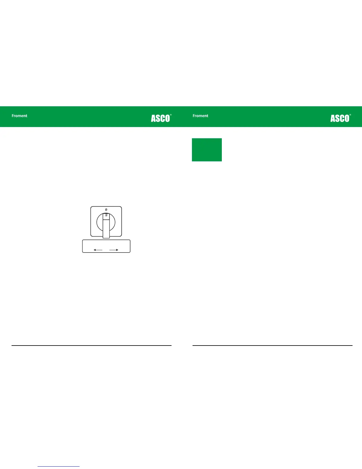
2. Select the source of supply for the fans and controls (External or Internal. See “External
supply wiring - the fan and controls power source” on page 2-9) by adjusting the fan
and controls supply selector switch (figure 3-7).
Figure 3-7 The fan and controls supply selector switch
3. Rotate the fan and controls supply isolator (Figure 3-6) to the On position.
4. As the control circuit power is applied, check that the both Start and Stop button
indicator lamps light during the lamp test. The Start lamp should go out after a few
seconds, leaving the Stop lamp on steadily.
5. Press the Start button. The Start button indicator will light and the Stop button
indicator will go out.
6. Now apply some load. You can do this using either the Hand-held (See “Manual Test
Mode” on page 4-24), the Sigma PC Load Control Software, or (if a load bank ID selector
switch is fitted) using the load bank emergency operation procedures described on
page 3-14.
7. Check the voltage, current and power readings are as expected and that none of the
load bank indicator lamps is flashing.
Supply for Fan and Controls
Change-over Switch
Internal OFF External
1 2
Chapter Three
3 - 13
8. Check the rotation direction of the fan. Movable load banks are fitted with automatic
phase rotation sensors and will adjust the direction of rotation accordingly. On static
units the fan may run in the reverse direction if the phases are wired in the wrong
sequence. Cold air should be drawn over the fan motor and through the element pack.
If the fan rotation is incorrect, switch o and isolate the load bank before making any
alterations.
9. Remove the load (press the O button on the Hand-held, or select <0> if you are using
the control panel).
The fan(s) should be allowed to run on for a few minutes until the equipment has cooled.
If a problem occurs during the load function test the Sigma controller may shut the load
bank down and the stop button will flash. Refer to Chapter Five for further advice.
Note: The Start lamp
will blink if you are
using the load bank
emergency operation
procedures described
on page 3-14.
Load Bank Operation