3 - 10
Warnings. A warning will alert you to an abnormal condition such as high temperature, but
will allow the unit to continue to run if required.
General load bank warnings are indicated by the Stop indicator lamp flashing continuously.
A warning related to the Supply-on-Test will result in the Supply-on-test indicator lamp
flashing (See “Warnings” on page 5-7 for more details). Depending on the nature of the
fault, the Hand-held unit may display a message.
To reset the error condition. Clear the cause of the fault and press the Stop button
followed by the Start button. The load bank will resume operation if the fault has been
cleared correctly.
The following table summarises the indicator lamp operation:
Chapter Three
Start Stop Supply-on-Test Description
O O O Load bank power supply o.
On On On Start up lamp test.
O On On
Load bank in stopped state, ready for start.
Supply-on-Test healthy.
On O On Load bank is operational. Supply-on-Test healthy.
- - Flashing
Supply-on-Test fault warning. The load bank will
remain operational and can be operated if required.
O Flashing -
Load bank in error condition. If the error occurs when
the load bank is operating the load bank will shut
down in a controlled fashion.
On Blinking -
Load bank warning - general fault. The load bank will
remain operational and can be operated if required.
Warning! The Supply-
on-Test lamp will glow
steadily to indicate that
the supply is connected
correctly. However, it is
important to note that it
only operates when the
fan and controls supply
is connected, and that
indicator bulbs can fail.
If the lamp is o this
does not indicate that
the Supply-on-Test is
disconnected, or that it
is safe to work on.
3 - 11
Emergency Shutdown Procedures
The load bank provides two methods of quickly shutting down the load bank in an
emergency:
Emergency stop button. The emergency stop button, located by the control room door,
is a latching mushroom type push button. Its eect on the load bank when operated is the
same as that of the Stop button (see below). The load is removed and the fan will stop
running, but the control system remains powered. Twist to reset the switch after it has
been operated. The Start button will not re-enable the control system until the switch has
been reset.
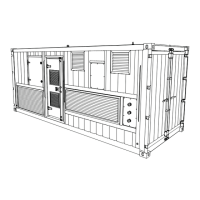
The Fan and Controls Supply Isolator. This is a two position switch which isolates the
power supply to the fan and controls when it is in the o position. It can be used to perform
an emergency stop, but it can also be padlocked in the o position and this means it can
be used to secure the load bank from unauthorised operation.
Figure 3-6 The Fan and Controls Supply Isolator
The Stop Button. Pressing the Stop button will result in an immediate shut down in a
similar way to the Fan and Controls Supply Isolator, but with one important dierence. The
load will be removed, the fan will stop running and the control system will be disabled, but
it will still be powered. To re-enable the control system, simply press the Start Button.
Warning! If the fan is
stopped when the load
elements are hot the
temperature with the
load bank will increase
considerably. The load
bank is designed to
withstand this without
damage, but the hot air
that builds up inside the
load bank could prove
to be a hazard. Please
ensure that the fan out-
let is kept clear when
the fan is restarted.
Load Bank Operation
Warning! Operating
the Fan and Controls
Supply Isolator or Stop
Button does not isolate
the Supply-on-Test
from the load bank
wiring. Some of circuits
within the load bank will
remain live.