5 - 6
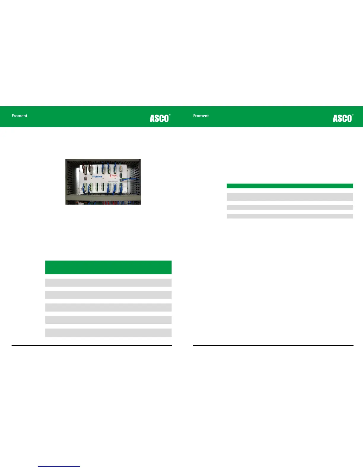
Sigma 2 Load Bank Status Display
The load bank status is displayed on the seven segment LED located on the Sigma 2 load
bank module.
Figure 5-1 The Sigma 2 control unit showing LED display
During operation the LED decimal point flashes every second.
If the decimal point is not flashing then a software problem is likely. Cycle the fans and
controls power supply o and on to restart the Sigma 2 controller and clear the fault.
Sigma 2 Normal Operation
In normal operation a single character status code is displayed on the LED:
Code Load Fan
Hand-
held (or
PC)
Description
. O O Emergency Stop.
0. O O None
Load bank running. Switch (or remote modbus)
control or Hand-held (or PC) not plugged in.
1. O O Ok Ready to apply load from Hand-held (or PC).
2. O On None
Fan running - decade switch (or remote modbus)
control.
3. O On Ok Fan running - Hand-held (or PC) control.
4. On O None
Fan starting - decade switch (or remote modbus)
control.
5. On O Ok Fan starting - Hand-held (or PC) control.
6. On On None
Load applied - decade switch (or remote modbus)
control.
7. On On Ok Load applied - Hand-held (or PC) control.
P. Ok
‘Setup’ mode. Sigma load bank setup/diagnostic
program running.
n. Load bank firmware upgrade in progress.
Chapter Five
5 - 7
Warnings
If an event occurs that generates a warning the load bank Stop button lamp will begin to
blink and a warning code sequence will be displayed on the Sigma 2 control unit LED. Each
character in the four step sequence is displayed for 500ms with the code repeating every
2s. The end of the sequence is indicated with the decimal point only.
Three digit warning codes start with H as the first digit. The second digit indicates the
operational status as follows:
Code Description
H0- High temperature warning.
H1- Load step error - faulty step disabled. Press and hold the load bank ‘Stop’ button for 6
seconds to re-enable the load steps.
H2- Communications to Hand-held (or PC) intermittent.
H3- Supply-on-test wiring incorrect.
H4- Supply-on-test phase rotation error.
H9- Load bank setup corrupt – using backup data.
Maintenance & Troubleshooting