Chapter One
1 - 4
Introducing Froment Load Banks
1 - 5
Introducing Froment Load Banks
Froment load banks are purpose designed to provide all of the facilities needed to quickly,
safely and reliably test generating equipment with outputs up to several megawatts.
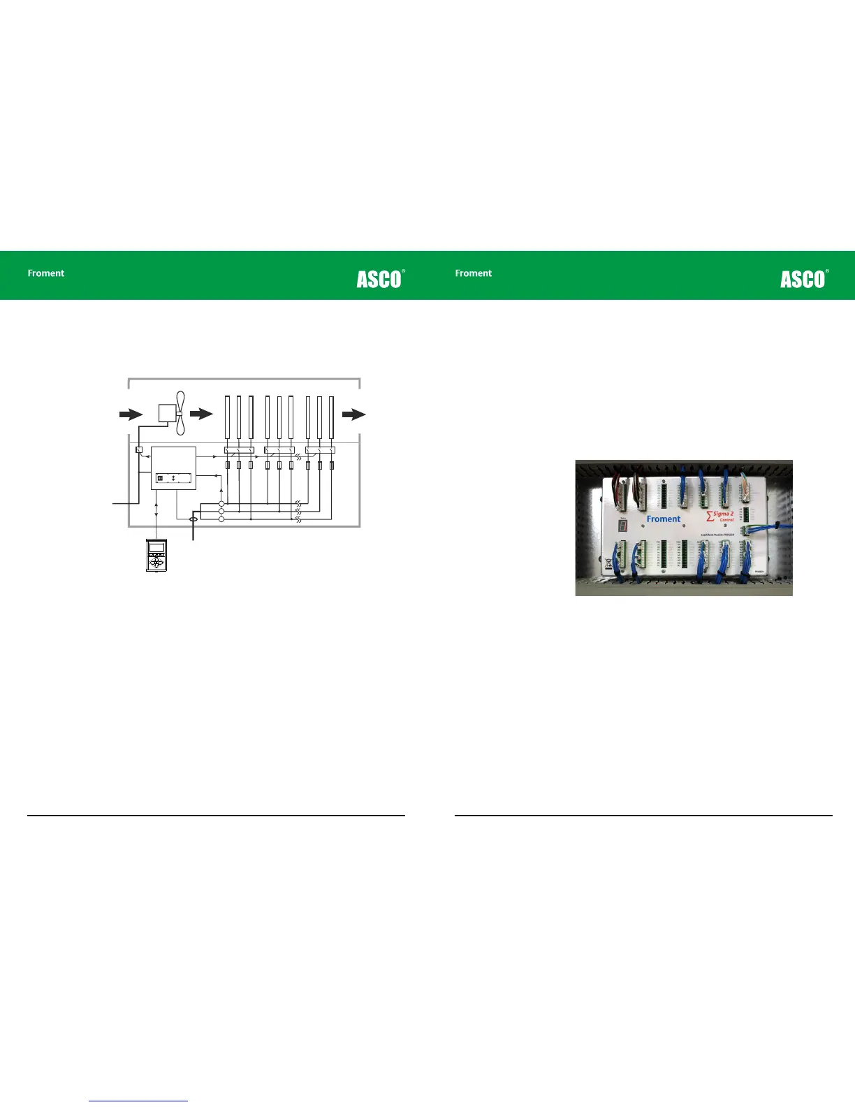
Figure 1-2 Froment load bank core components
There are many variations between dierent Froment load bank models, but Figure 1-2
shows a simplified schematic of the core components to be found in most units.
The diagram contains:
• An array of load elements grouped in small steps that are individually activated by
switchgear to allow the load applied to the generator to be precisely controlled.
• A fan and duct forced air system which ensures that the heat generated during testing
is vented safely to atmosphere.
• Fuses and safety interlocks that ensure that the test can be shut down in a controlled
fashion if any problems occur.
• A microprocessor based control and three phase instrumentation system connected to
a number of highly accurate voltage and current transformers. This provides automatic
precision control of the test and allow the results to be displayed with better than 0.5%
accuracy.
Cold air
inlet
Fan
motor
Air duct
Fan
contactor
Step 1Step 1Step n
Load Elements
Hot air
outlet
Supply-on-test
Remote control
unit
External supply for
fan and controls
Sigma II
load bank
controller
Front panel controls
Load
contactors
Fuses
Phase
rotation
sensor
Current/Voltage
Transformers
Froment Load Bank Control Options
Reliable testing requires precise control of the load applied to the generator and accurate
real-time measurement of the generator’s output.
To achieve this, most Froment load banks are fitted with a Sigma 2 load control system.
Sigma 2 is a microprocessor-based control and instrumentation system specifically
developed for load bank applications.
Sigma 2 provides precise control over the operation of each load element during the test
whilst simultaneously measuring the results. The unit also provides safety monitoring and
interlocks which shut down the load bank safely should a problem occur.
Figure 1-3 Sigma 2 load bank control unit.
User control interfaces
The wide variety of dierent applications for load banks require a wide variety of user
control interfaces. These range from a very basic switch controlled system through to
sophisticated computerised control, instrumentation and data logging systems.
All Froment load banks are supplied with a built-in switch plate which contains a Fan and
Controls Supply Isolator, Start and Stop switches and (for Sigma2 controller equipped
units) Sigma control cable connectors.
The switch plate may contain other controls, depending on the specific load bank variant.
Depending on the application, the Sigma controller unit can be operated by a number of
dierent control interfaces. These include: