Chapter One
1 - 14
Introducing Froment Load Banks
1 - 15
Figure 1-10
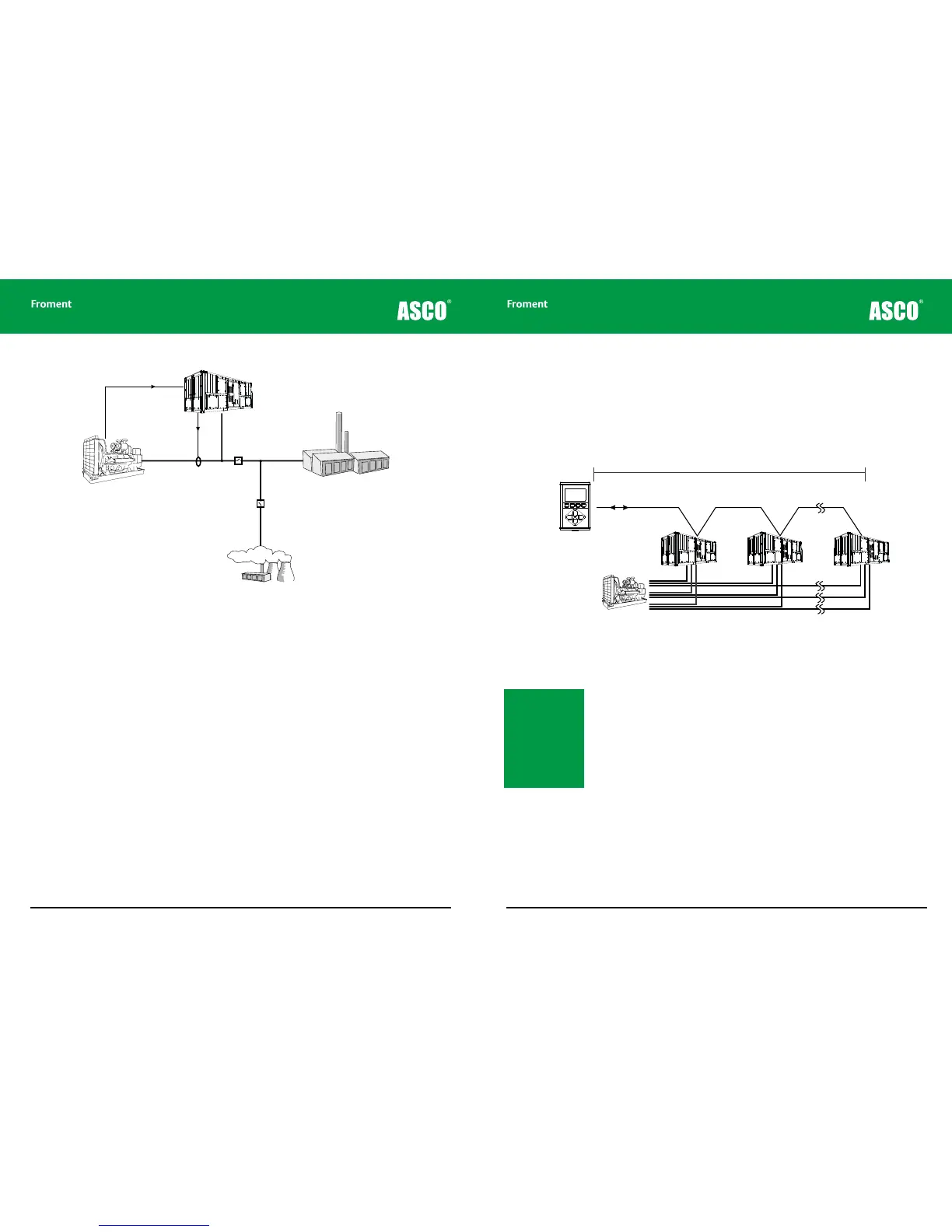
Example layout for a typical Site Load Correction system.
The load bank starts up when the generator begins to operate and its control circuits
begin to monitor the output current. If this is below a certain set point then the load bank
will slowly apply additional load to bring the generator within the optimum range. If the
current increases in response to an increase in site load the load bank will remove load
accordingly. The load bank can do this very quickly in response to sudden changes of site
load such as a lift or pump motor starting up.
SLC is a specialist application for a load bank and it requires careful configuration. Please
contact Froment for more information and advice if you are thinking of configuring your
load bank for SLC.
Using Multiple Load Banks
Froment’s Sigma control system allows up to fourteen load banks to be interconnected and
controlled from a single terminal as if they were a single unit. This means that multiple load
banks can be combined to match particularly large generating sets, or that a combination
of resistive, capacitive or inductive loads can be mixed for special purpose or one-o tests.
Figure 1-11 Connecting multiple load banks
One example of the use of multiple load banks might be where a purely resistive load bank
is to be permanently installed for ongoing routine maintenance engine tests. A load bank
with inductive elements could be added for a short period so that commissioning and
acceptance tests can be carried out.
Note: When multiple
load banks of dierent
capacities are used the
load applied is shared
proportionally depend-
ing on the ratio of the
load banks’ capacity.
The cable sizes for the
Supply-on-Test must
take this into account.
Control Signal
Load Bank
Generator
Current
Transformer
Site Load
© NJ Froment & Co. Ltd. This document may not be copied
or disclosed in whole or part without prior writ ten authority.