3 - 8
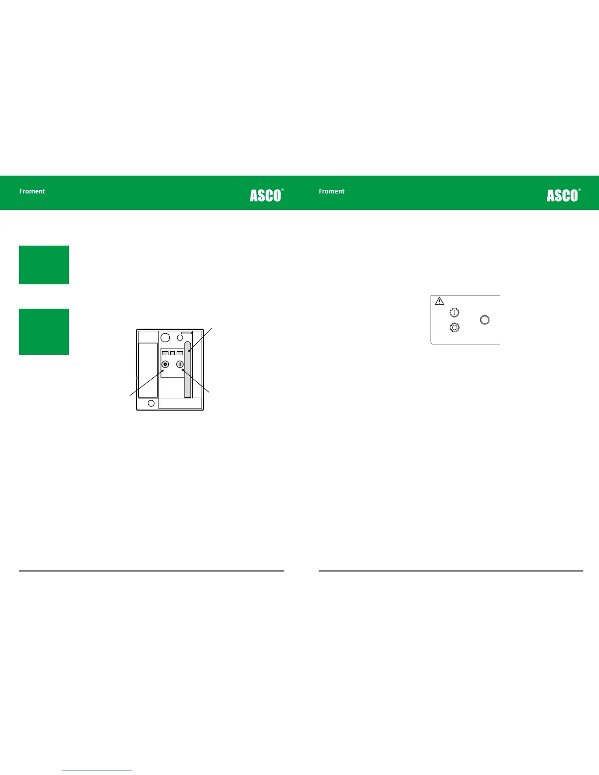
Operating the optional air circuit breakers (ACBs)
The circuit breaker spring motor must be fully charged before its contacts can be closed:
1. Pull on the charging handle and operate it through the full range of its stroke nine
times.
2. The lever will slacken after the ninth stroke, indicating that the spring is fully charged.
3. Lift the clear plastic safety cover and press the green I button to close the circuit
breaker contacts.
4. Lift the clear plastic safety cover and press the red O button to open the circuit breaker
contacts.
Figure 3-4 ACB operating controls
Chapter Three
Spring motor
charging handle
Close contacts
button
3 - 9
Status indicator lamp operation
The control panel contains a number of status indicator lamps. These include a lamp (two
lamps in the case of the 8400) which indicates the status of the Air Circuit Breakers (ACBs).
There is also a lamp which indicates the status of the Supply-on-Test. The Start and Stop
indicator lamps, located in the Start and Stop/Reset push buttons, and the Supply-on-Test
status lamp work together to provide a visual indication of the load bank’s operational
status.
Figure 3-5 The Start and Stop indicator lamps located in the control panel push buttons.
When the load bank controls are first powered up all indicators will illuminate. This provides
a lamp test and indicates that the Sigma 2 processor’s self test sequence is running. When
the self-test sequence has completed successfully the Start lamp is extinguished and Stop
lamp will be illuminated steadily.
If the Air Circuit Breakers are closed the corresponding status lamps will light. If the
Supply-on-Test has been connected correctly the Supply-on-Test status lamp will also
glow steadily.
If no other lamps are lit the load bank is now operational and waiting for the Start button to
be pressed. Pressing the Start button activates the control system and will illuminate the
Start indicator. The Stop lamp will extinguish.
Fault Indicators
The indicators flash to provide a visual indication of faults detected by the Sigma controller.
Faults are classified as either a warning or as an error.
Errors. These are serious fault conditions which result in the load bank performing a
controlled shut down when they occur.
If an error occurs the Start indicator lamp will be extinguished and the Stop indicator
lamp will begin to flash. An error code will be displayed on Sigma controller LED (see See
“Sigma 2 Load Bank Status Display” on page 5-6 for more details). If an Hand-held unit or
PC system is connected to the load bank the error message will be displayed on the screen
(See “Sigma 2 Load Bank Status Display” on page 5-6 for more on this).
Load Bank Operation
Note: The spring motor
generates a loud noise
when opening and
closing the contacts.
This is normal operation
and does not indicate
a fault.
Note: When the ter-
minal link plates are
in use the contacts on
both ACBs should be
closed before any load
is applied.
PA10251
Warning!
High Leakage Current
The Frame of this equipment must be bonded to the
protective earth terminal of the supply on test.
A conductor of no less than half the total cross-sectional
area of the supply conductors should be used.
LOAD BANK NUMBER
When controlling more
than one load bank, each
must have a different
number set on this switch.
Sigma 2
Control
∑
All doors must be shut
and guards fitted before
running this equipment.
Remove load and allow
elements to cool before
stopping the fan.
START
STOP/
RESET
Supply-on-Test
Status
Circuit Breaker
#1
CLOSED
Circuit Breaker
#2
CLOSED
Voltage
Metering
Source
INT EXT
Off: No Voltage
On: Normal Operation
Flashing: Out of Limits
1
2
3
4
5
9
7
8
10
11
0