2 - 10
Chapter Two
2 - 11
Load Bank Installation and Setup
If you are making use of this external supply socket, switch the 3-position supply selection
switch to the “External” position.
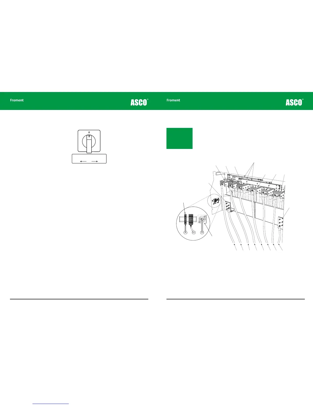
Figure 2-3 The supply for fan and controls supply selector switch.
If there is no independent power supply available (and the Supply-on-Test is the correct
voltage and frequency rating) then you can power the load bank from the Supply-on-Test
by setting the supply selection switch to the “Internal” position.
8000 SERIES load banks are fitted with an automatic phase rotation detection system to
ensure that the fan rotates in the correct direction irrespective of how the phases are
connected.
Anti-condensation heaters and lighting supply
The control room is fitted with lighting, single-phase socket outlets and anti-condensation
heaters for the switchgear cabinets. It may be necessary to have these powered
continuously, even when the normal fan and controls supply is not available. Because of
this the control room is fitted with a single phase AC line input connector which can be
used to provide power for this equipment.
To connect the AC line connector to the control room equipment set the lighting changeover
switch to the External position.
Notice that when the lighting changeover switch is in the Internal position the control room
equipment is powered by the fan and controls supply. This can be the external supply or
the Supply-on-Test — depending on the fan and controls supply selector switch position.
Supply for Fan and Controls
Change-over Switch
Internal OFF External
1 2
Connecting the Supply-on-Test
The cables for the Supply-on-Test can be fed into the load bank through cable sock
openings in front of the power terminal compartment, or through the bottom of the
container (suitably sized glands must be fitted to the aluminium gland plate provided).
The cables are connected to the ears hanging down from the terminal bars as shown in
Figure 2-4.
For the 8400, where there are two sets of terminal bars, multiple supply cables should be
used to ensure that the supply is distributed evenly between the terminals.
Figure 2-4 8400 power terminal compartment
Instrumentation neutral. 8000 SERIES load banks are provided with an instrumentation
neutral only. The terminal is not connected to any of the load elements and is provided for
connection to instrumentation only. If the Supply-on-Test has a neutral terminal it should
be connected to the load bank neutral terminal to achieve maximum instrumentation
accuracy.
Note: The terminal bars
can accept both copper
or aluminium cables. Re-
fer to local regulations
and size them accord-
ingly.
Optional Air