Chapter Two
2 - 8
Load Bank Installation and Setup
2 - 9
Electrical Installation
The electrical installation for a 8000 SERIES load bank consists of making connections for
the Supply-on-Test, an external supply used to power the load bank’s fans and control
system and, finally, a single phase supply that provides power for the control room lights
and cabinet heaters.
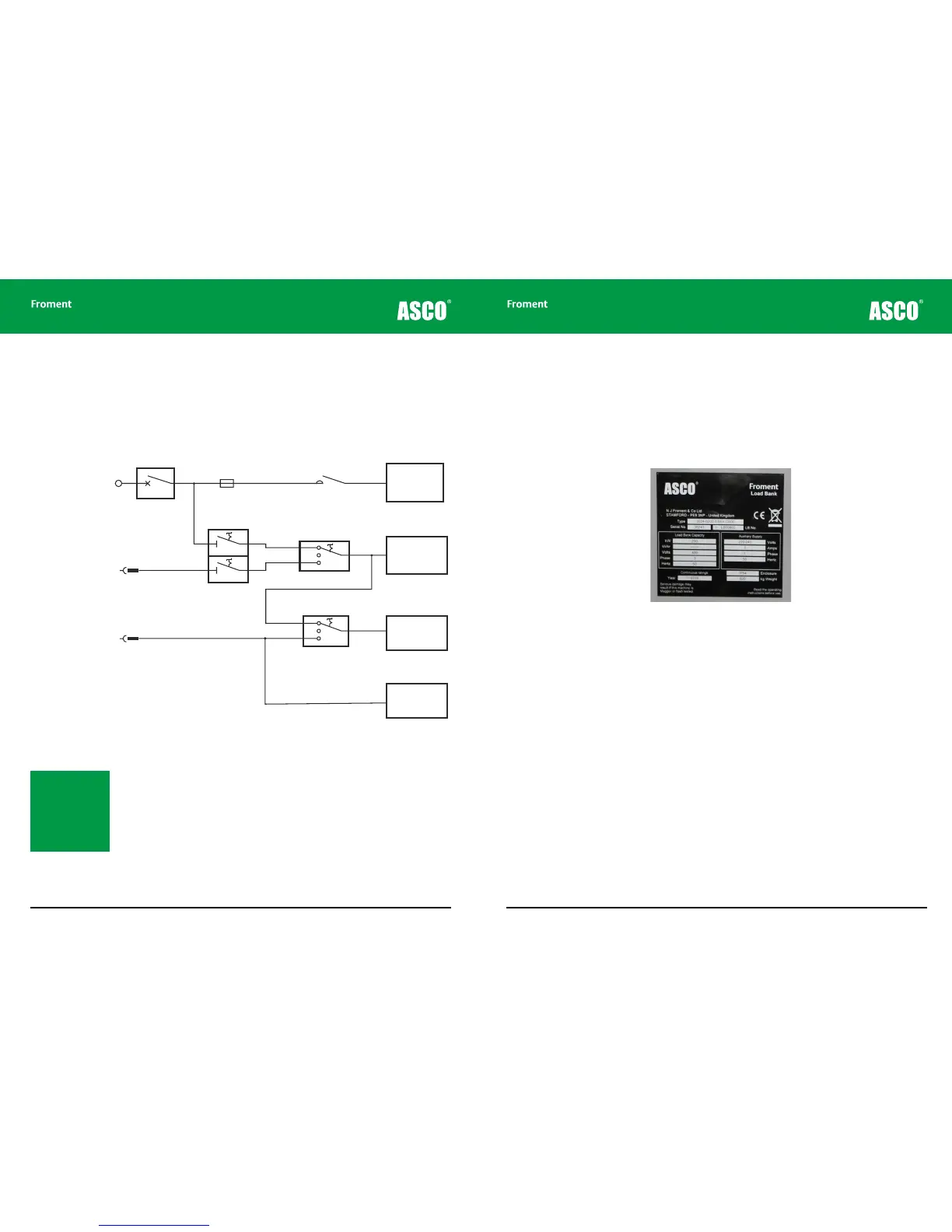
Figure 2-1 An 8000 SERIES load bank can have up to three separate power sources.
The requirements for these three supplies are described separately here, but the following
general points apply in all cases:
• The work must be carried out by a person with the appropriate training, qualifications
and experience.
• All cables should be appropriately rated and installed in accordance with current
standards and accepted practice.
• The connections to the load bank may be intended to be temporary, but it is essential
to apply the same standards to the cable glands and terminations as if the installation
were permanent.
Note: The Load Bank
supply cables must be
protected by a Short
Circuit Protective
Device (SCPD), which
is suitably rated to the
capacity of the supply
cables.
Supply-on-Test
Power
Terminations
Breaker
Load Fuses
Load Contactors
Load Elements
Fan & Controls
+
Socket Outlets
External Supply
for Fan
and Controls
Supply for
Anti-Condensation
Heaters and
Lighting
Control Circuit Emergency
Stop / Disconnect Switch
Supply For
Fan & Controls
Changeover Switch
Lighting
Changeover
Switch
Control Room &
Terminal
Compartment
Lighting
Anti-Condensation
Heaters
External
EXT
Internal
INT
OFF
OFF
3Φ
3Φ
1Φ
1Φ
Air
Voltage and frequency ratings
It is important to realise that the external supply required for the fans and controls may be
of a dierent voltage or frequency from the Supply-on-Test. The voltage and frequency
ratings are specific to the equipment supplied and are shown on the rating plate.
Exceeding the voltage ratings or supplying the wrong frequency can cause damage to the
load bank so please check the plate carefully before starting the installation.
Figure 2-2 Consult the load bank’s rating plate for voltage and current ratings
before making connections
External supply wiring - the fan and controls power source
We recommend that you use an external power supply that is independent of the Supply-
on-Test. This ensures that the load bank will continue to operate without interruption if the
Supply-on-Test becomes unstable or fails.
Refer to the load bank’s rating plate for the external power supply requirements. The
supply must be capable of supplying the fan motor starting current, and must be fused
accordingly.
Connecting the external supply
The 8400 load bank is fitted with an external power input socket inside the control room.
The external supply socket for the 8300 is mounted externally (see appendix drawings for
the exact location).
Both types of load bank are fitted with a 3-position supply selection switch, which is located
in the control room. This switch is used to switch between the Internal and External power
supplies.