2 - 14
Chapter Two
2 - 15
Load Bank Installation and Setup
Basic Connection
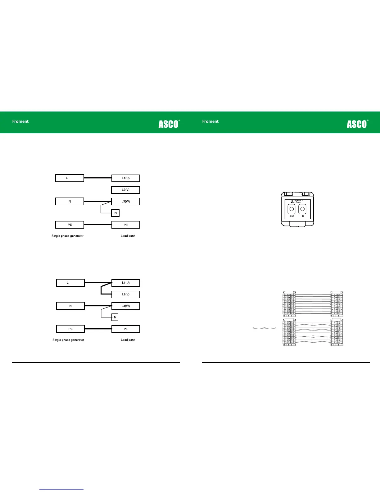
The basic connection shown in Figure 2-6 will give approximately 50% loading capacity
when the nominal load bank supply voltage is connected or 17% loading capacity when a
230V single-phase supply is used.
Figure 2-6 Basic connection for a delta configured single phase supply
Alternative connection
The loading capacity can be increased by linking together L1 (U) and L2 (V) as shown in
Figure 2-7.
Figure 2-7 Alternative Delta configured connection for maximum loading
Instrumentation
neutral
Instrumentation
neutral
In this case the connection will provide approximately 67% loading capacity when a 400V
single-phase supply is connected or 22% loading capacity when a 230V single-phase
supply is used.
Control System Connections
Load banks are usually operated using a Sigma control device connected to the Sigma
Control cable socket on the control panel. To connect the Sigma device simply plug the
control system control cable in to the front panel socket.
Figure 2-8 The Sigma control cable connector.
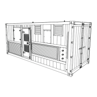
Remote panels for static load banks
Some load bank installations include a remote control station This duplicates some of
the controls on the main control panel and provides sockets for connecting the Sigma 2
control cable.
Remote station control panels are connected to the load bank using a set of terminals which
are located in either the main power termination compartment or the control compartment
(refer to the supplied drawings for details of the specific location and wiring).
Figure 2-9 Typical wiring for a remote station control panel.
OUT IN
Sigma 2
Control
∑
Fan and controls
supply isolator (Emergency Stop)
Fan and controls
supply source
selector
Manual stop/start
buttons
Sigma control
interface cable
sockets (in/out)
Load bank
number selector
Supply on test
status indicator
LB00060
LOAD BANK NUMBER
When controlling more
than one load bank, each
must have a different
number set on this switch.
Sigma 2
Control
∑
All doors must be shut
and guards fitted before
running this equipment.
Remove load and allow
elements to cool before
stopping the fan.
START
STOP/
RESET
Warning!
Isolator for fan
and controls supply only.
Other supplies may enter this load
bank. Isolate all before working on
this equipment.
Select “Internal” only when the
Fan & Controls Supply Selector
supply-on-test equals the control circuit
rated voltage and frequency.
OFF ExternalInternal
Supply-on-Test
Status
Off: No Voltage
On: Normal
Operation
Flashing: Out of
Limits