3 - 4
The Control Room
The control room houses the cabinets containing the load bank switchgear, the external
power supply sockets, a number of local controls and connectors for external equipment.
At the rear of the control room is a console, which provides a desktop surface for laptop
computers, monitoring equipment, etc.
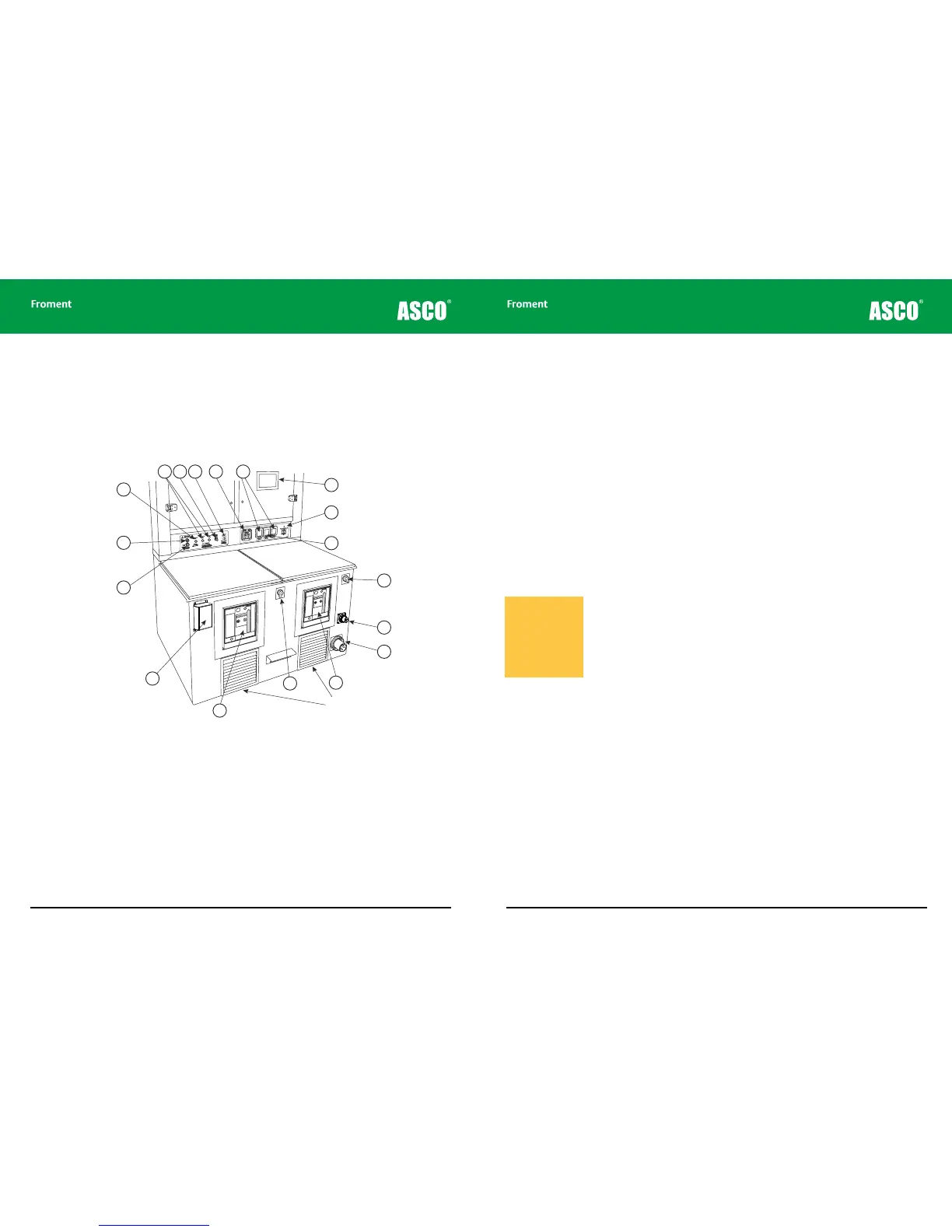
Figure 3-1 Typical 8400 load bank control room layout
Chapter Three
1. Stop/Reset button
2. Start button
3. Supply-on-test status indicator
4. ACB status indicators
5. Voltage metering selector switch
7. Sigma control system In/Out connections
8. Socket outlets
10. Lighting supply changeover switch
11.RCD
12. Supply for fan and controls changeover switch
13. Supply forAnti-Condensation Heaters and Lighting
14. External Fan and Controls Supply
15. Air contact breaker Duct #2
16. The Fan and Controls Supply Isolator
17. Air circuit breaker Duct #1
6. Load bank number selector
15
16
17
14
13
18
12
1
2
3
4
5
9
10
11
67 8
Important Note:
Do not obstruct Air Vents
3 - 5
The lower front surface of the console contains the following:
Supply for fan and controls changeover switch. This is used to select whether the fan
and controls power supply is to be provided from the external mains supply (External) or
from the Supply-on-Test (Internal).
Anti-condensation heaters and lighting supply. This connector is used when the
control room lighting and anti-condensation heaters are to be powered by an independent
external supply. This is a single-phase supply inlet connector — see the rating plate for
supply details (more details on page 2-10).
External fan and controls supply connector. For use when the fan and controls are to be
powered by an supply that is independent from the Supply-on-Test. This is a three-phase
supply inlet connector — see the rating plate for supply details.
Optional Air Circuit Breakers (ACBs). Some 8000 SERIES load banks are fitted with
optional spring motor powered air circuit breakers for the Supply-on-Test connections.
The 8300 has a single circuit breaker and the 8400 has two. Refer to the documentation
provided with the circuit breakers for further information.
Fan and controls supply isolator. This performs a similar function to the emergency stop
button located by the control room door. It is the “on” switch for the load bank control
system but can also be used to interrupt testing in the event of an emergency. When
operated it isolates the control circuit which immediately stops the fans and removes any
load.
The upper surface at the rear of the console contains two control panels and the load bank
System Monitor.
Load Bank Operation
Warning! The Fan and
Controls Supply isolator
does not isolate the
Supply-on-Test. Some
of the circuits within the
load bank may remain
live when the switch is
in the o position.