3 - 6
Main control panel
The main control panel for the load bank is located on the left at the back of the control
room. The specific controls provided can vary from model to model — the arrangement
shown in Figure 3-2 shows a typical configuration for the left hand side of the panel and
Figure 3-3 shows a typical arrangement for the right hand side.
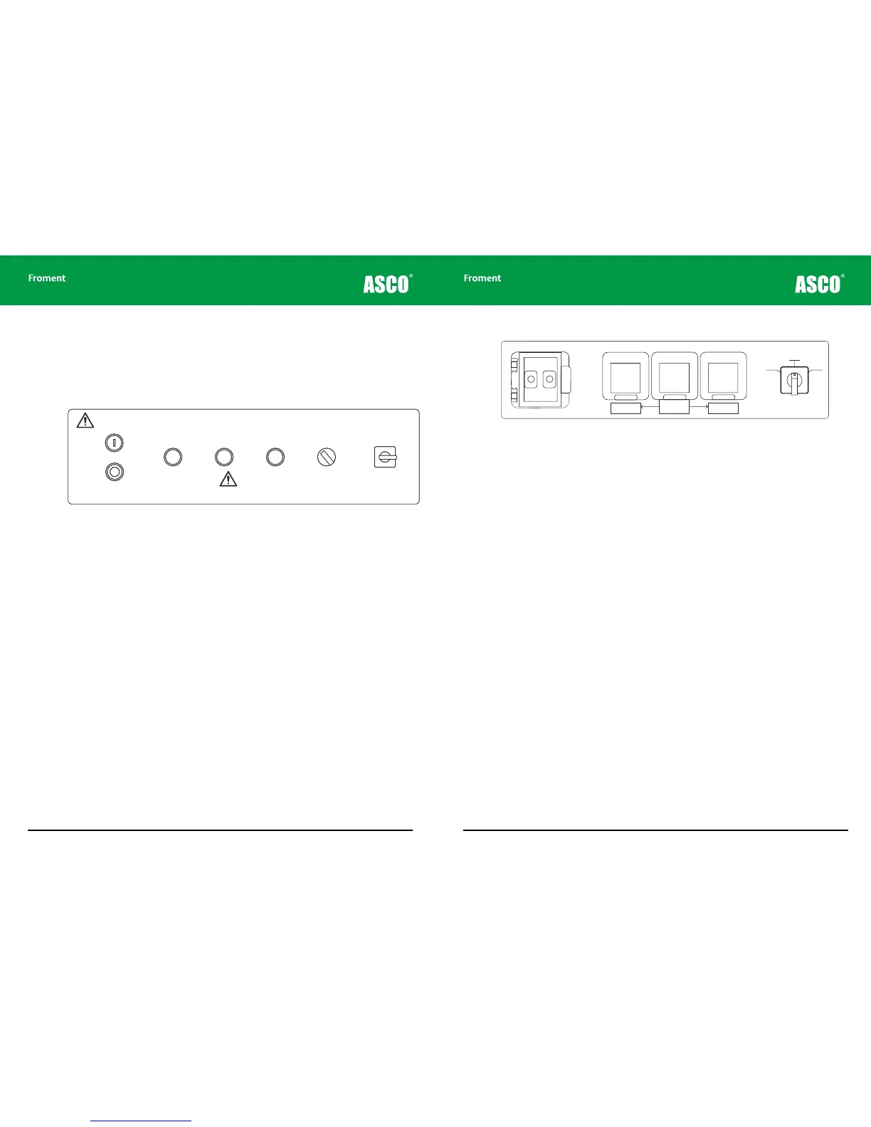
Figure 3-2 Typical arrangement of lamps and switches for 8400 left hand control panel
Start Stop/Reset buttons. The Start and Stop push buttons are used to enable and
disable the load bank’s control system. They are also used to reset any error conditions
(such as over-voltage or over-temperature) that may have caused an automatic shutdown.
Both buttons contain indicator lamps that show the load bank’s status.
Pressing the Start button enables the control system, but may not start the fan or apply
load unless the control system requests it.
Supply on test status indicator. These indicator lamps provides information about the
status of the Supply-on-Test.
ACB status indicators. These light up when the contacts on the associated ACB are
closed.
Voltage metering source selector. This switch is used to select the source used by the
load bank for voltage metering.
Load bank number selector. This rotary switch is used to configure a unique load bank
number, which identifies the unit to the control system when multiple load bank units are
used together. It can also be used as an alternative control switch if the Hand-held or other
Sigma controller is not available. See “Load bank emergency operation” on page 3-9 for a
more detailed explanation of how to do this.
Chapter Three
PA10251
Warning!
High Leakage Current
The Frame of this equipment must be bonded to the
protective earth terminal of the supply on test.
A conductor of no less than half the total cross-sectional
area of the supply conductors should be used.
LOAD BANK NUMBER
When controlling more
than one load bank, each
must have a different
number set on this switch.
Sigma 2
Control
∑
All doors must be shut
and guards fitted before
running this equipment.
Remove load and allow
elements to cool before
stopping the fan.
START
STOP/
RESET
Supply-on-Test
Status
Circuit Breaker
#1
CLOSED
Circuit Breaker
#2
CLOSED
Voltage
Metering
Source
INT EXT
Off: No Voltage
On: Normal Operation
Flashing: Out of Limits
1
2
3
4
5
9
7
8
10
11
0
3 - 7
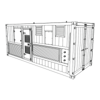
Figure 3-3 Typical arrangement for 8400 right hand control panel.
Sigma control system In/Out connections. These provide the plug-in connectors for
the Sigma interface cable. This allows for remote control and provides access to all of
the advanced control and instrumentation features provided by the Hand-held, Sigma PC
Load Control Software or the Sigma Modbus interface. It also allows multiple load banks to
be connected together and simultaneously controlled from the same control device.
Power outlet sockets and RCD. The panel contains two socket outlets that can be used
to power personal computers or test gear (maximum 5 amps).
Lighting supply changeover switch. This selects whether the fan and controls power
supply is to be provided from the external mains supply (External) or from the Supply-on-
Test (Internal).
System monitor
The optional System Monitor is a touchscreen based operator interface panel that
provides a number of important system maintenance functions for the load bank. These
functions include providing a real-time display of the load bank’s operational status, with
instrumentation read-outs for both the supply on test and the external supply.
In addition, the System Monitor provides detailed diagnostic information regarding the
status of the control system’s inputs and outputs, and full details of any error messages
that may occur.
The use of the System Monitor is described in more detail in Chapter Five.
Load Bank Operation
Internal
RCD Protection
(5A max)
Socket Outlet
(5A max)
Socket Outlet
(5A max)
OUT IN
Sigma 2
Control
∑
OFF
EXTINT
Lighting Change-over
Switch