A - 2
8300 - Installation Diagrams
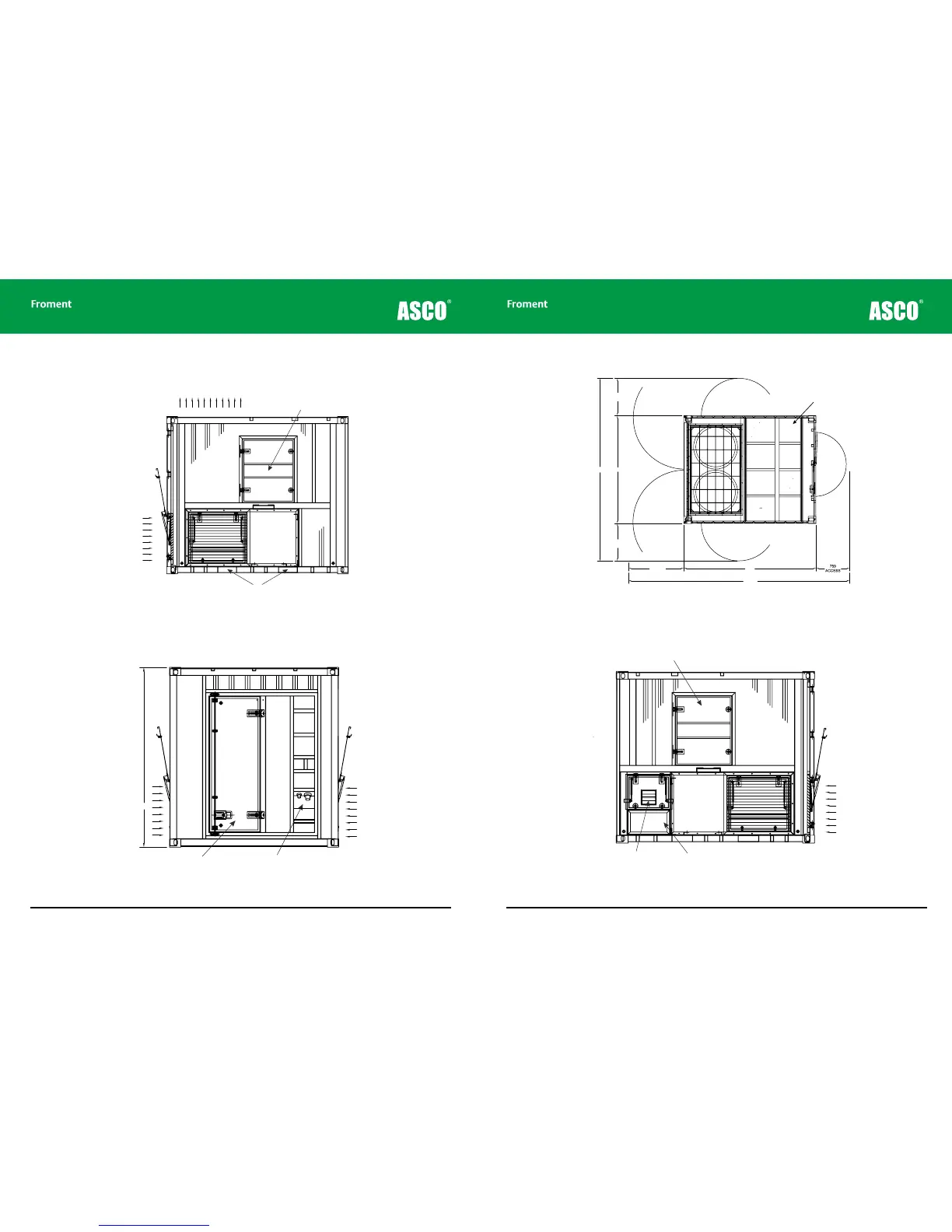
Figure A-1 8300 - Side view showing maintenance access and the fork lift pocket locations.
Figure A-2 8300 - End view showing control room door access.
Appendices
A - 3
Appendices
Figure A-3 8300 - Plan view showing access clearance requirements
Figure A-4 8300 - Side view showing cable entry sock location
Fork lift pocket centres (1000)
Maintenance access door