2 - 12
Chapter Two
2 - 13
Load Bank Installation and Setup
External voltage metering source. This input connector is used to connect the load
bank’s instrumentation directly to the Supply-on-Test. This provides more accurate
instrumentation, avoiding problems of voltage drop when long supply cables are used.
Refer to the wiring diagrams supplied with the load bank for connection details.
Protective earth connection. Earth conductors must always be bonded to the frame of
the Supply-on-Test and connected to the grounding terminal of the load bank (marked
PE). The cables used must be suitably sized for the Supply-on-Test.
Additional frame bonding points are provided on the corners of the container.
8400 link bars
The 8400 load banks have two sets of input terminals, one for each load bank section.
As supplied, these are linked by bars arranged horizontally between each phase. These
bars can be removed to allow the load bank sections to be supplied independently using
unmatched transformers.
Figure 2-5 MCB linking bars in position on 8400
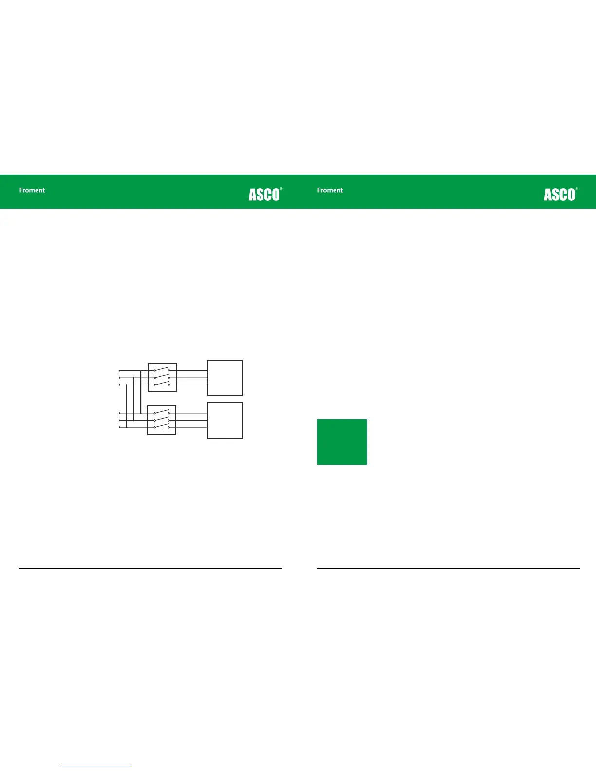
ACB remote trip
The optional Air Circuit Breaker (ACB) remote trip terminals are provided to allow a remote
emergency stop button to be installed on load banks where an ACB is installed. Shorting
these terminals during operation will cause the ACB contacts to open immediately, isolating
the Supply-on-Test.
The fans and controls will continue to operate if their power supply is from an external
source. However, the control system will detect the ACB’s trip and will initiate a controlled
shutdown.
Supply
on
test
Supply
on
test
ACB 1
ACB 2
Load
Elements
Load
Elements
Optional Air Circuit Breakers
Supply-on-test wiring - general points
• The cable lugs should be clamped directly to the bus-bar by means of the bolts
provided and all securing nuts must be tight.
• It is good practice to route the three phase conductors in a close trefoil layout, held
together with regular cable-ties. This minimises stray magnetic fields from the cable
array, and reduces inductive losses in the cables. In the event of a high fault current
flowing this arrangement minimises the risk of sudden and violent cable movements.
• To eliminate induced magnetic fields and their associated eddy currents and heating
eects all three phase conductors must pass through the same opening into the load
bank terminal area.
• If the connections are made using more than one conductor for each phase connection
all the cables on any one phase should be of exactly the same length, and laid along
a similar route. To minimise eddy current losses, etc. the conductors should be
distributed equally between the terminals and the cable entry openings.
• The Load Bank supply cables must be protected by the Short Circuit Protective Device
(SCPD), which is suitably rated to the capacity of the supply cables.
Making connections for single-phase operation
3-phase load banks can be used for testing single-phase supplies. The method of
connection (and the load available) will vary depending on the rating of the load bank and
the supply voltage and frequency.
Automatic single phase connection check
The Sigma controller checks and provides confirmation when a single-phase supply is
connected to the bus-bars correctly. If the system detects an incorrect connection then
the hand-held terminal will indicate the required connection method. The Sigma control
software will also automatically adjust the loading to take account of the connection
options and the supply voltage.
Single phase wiring
8000 SERIES load banks have only an instrumentation neutral (marked N in the terminal
compartment). This is not connected to any of the load elements is not capable of carrying
any load current. Because of this, single-phase operation is achieved by connection
between two phase terminals, one of which is used as neutral. The neutral terminal is
connected only for instrumentation purposes.
The maximum permissible single-phase supply voltage is 100% of the 3-phase load bank
rated voltage, but the maximum loading capacity depends on the connection used.
Note: 8000 SERIES load
banks are fitted with a
3-phase fan motor and
an external 3-phase
mains input will be
required for the controls
and fan supply.