Chapter Four
4 - 4
Connecting the Hand-held to the Load Bank
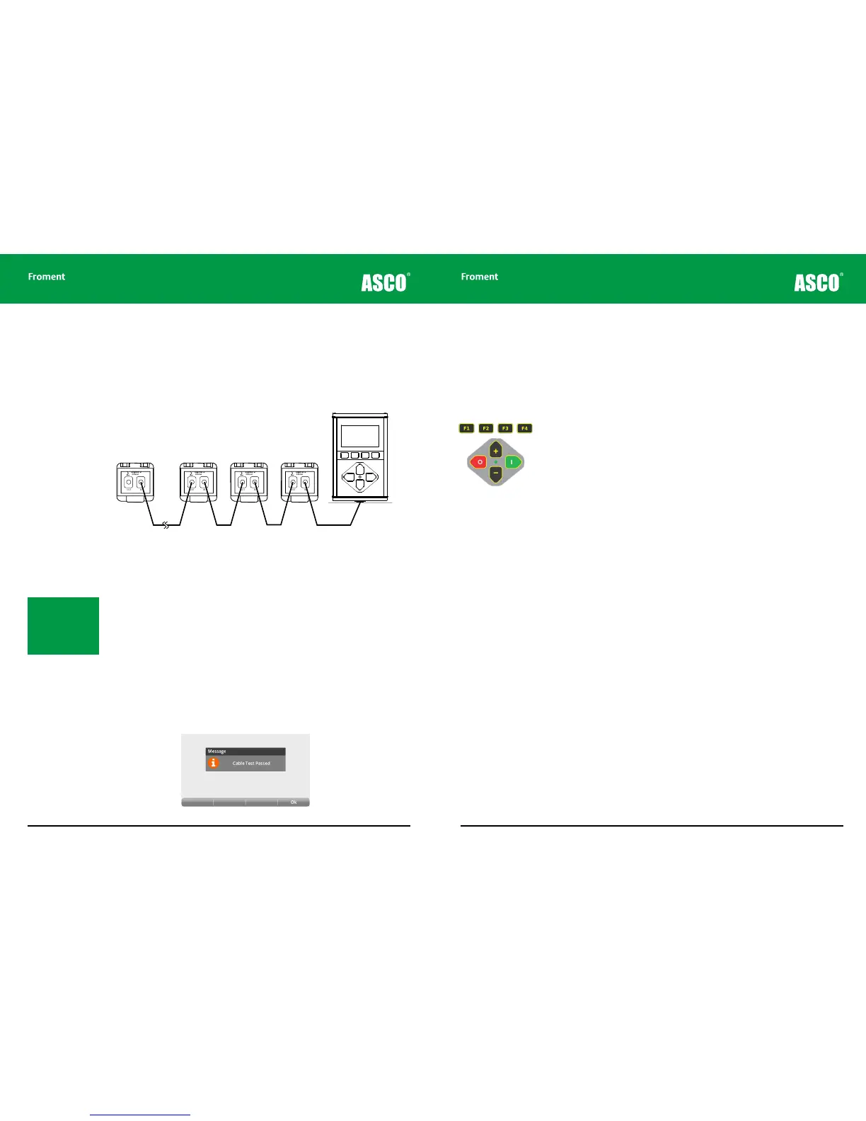
The Hand-held connects directly to the load bank’s Sigma control “in” socket using a
Sigma control cable which can be up to a kilometre in length.
The Hand-held can connect to and control up to 14 load banks at the same time. The load
bank units are interconnected using a daisy chain arrangement as shown in Figure 4-2.
Figure 4-2 The Hand-held Sigma control cable connecting multiple units in a daisy
chain arrangement
Setting the load bank number
Each load bank connected must have a unique number in the range from 1 to 14. The default
number for a particular load bank is assigned during manufacture or on commissioning. If
there is a number selector switch on the load bank this can be used to change the number
to any value from 1 to 11. Setting the selector switch to 0 selects the default number as
stored in the load bank.
Sigma control cable testing
With the addition of a small, mains powered adaptor, the Hand-held can be used as a
Sigma control cable test unit. This provides a fast method of identifying control cable
faults. Contact Froment’s Sales department for more details on this.
OUT IN
Sigma 2
Control
∑
OUT IN
Sigma 2
Control
∑
OUT IN
Sigma 2
Control
∑
OUT IN
Sigma 2
Control
∑
Load Bank
n
Load Bank
3
Load Bank
2
Load Bank
1
Note: Voltage and fre-
quency instrumentation
displayed on the Hand-
held display is taken
from the load bank with
the lowest number.
© NJ Froment & Co. Ltd. This document may not be copied
or disclosed in whole or part without prior writte n authority.
4 - 5
The Hand-held Keypad
The keypad contains eight membrane switches and a single LED indicator. The switches
provide four function keys (marked F1 to F4) arranged below the screen and a quadrant of
four control keys arranged around the LED.
The function keys
The operation of the function keys is context dependant. A menu bar, containing labels
for each of the keys, appears at the bottom of the screen. The labels for each function key
change to indicate the function (PAGE, EDIT, etc.) in the particular context.
The quadrant keys
The four quadrant keys are used to make adjustments, to apply or reject a load, or to start
an automatic test sequence if one is configured.
The + and – keys are used to increase or decrease values that are highlighted or displayed
on screen.
Pressing I applies load if in Manual Test mode, or starts an automatic test if in Automatic
Test Mode.
If a load is already applied pressing I forces the Hand-held to carry out a load correction
(that is to say that it will adjust the number of load elements applied to correct for changes
in voltage or temperature, etc.).
Pressing O at any time will reject the load or abort any automatic load test that is running.
If the load is set to ramp down on reject (indicated by fast blinking of the green LED)
pressing O a second time will drop the remaining load immediately.
The LED status lamp
The LED indicator provides feedback of the current load status:
Continuously On. Load applied (manual mode) or test sequence paused (automatic mode)
Half Second Blink. Automatic test running
Rapid blinking. Ramping down on reject
Chapter Four