V
2.2.2.3 USE OF OVERCOUPLING IN TUNED
CIRCUITS
Another method of obtaining a flat-top re-
sponse with tuned circuits is to overcouple.
If two tuned circuits are tuned to the same
frequency the overall response of the coils is
determined by the amount of coupling be-
tween them. Figure 2.10 shows typical curves
obtained by undercoupled, critically coupled
and overcoupled coils. In the overcoupled
case, the center dip in response
will increase
as the coupling is increased lei spread the
peaks. The maximum amplitudes will
also begin to decrease as overcoupling in-
creases. This principle is used in chroma
bandpass transformers. Usually, two tuning
slugs are found in these transformers. One
adjusts the coupling between windings and
the other is a tuning adjustment. Sweep
alignment of this type of transformer is prac-
tically a must. In this application as well as
in i-f alignment, a compromise between gain
and bandwidth is always made. The ampli-
tude of the response curve can be greatly
increased by tuning all adjustments for max-
imum amplitude, but this will be at a sacri-
fice in bandwidth which is equally important
in proper circuit performance.
CRITICALLY
COUPLED
I
OVERCOUPLED~-,.....,u. \L~......, UNDERCOUPLED
HEAVILY
_,,- OVERCOUPLED
Figure 2.10 Efiects of Coupling on Overall Response
of Two Tuned Circuits
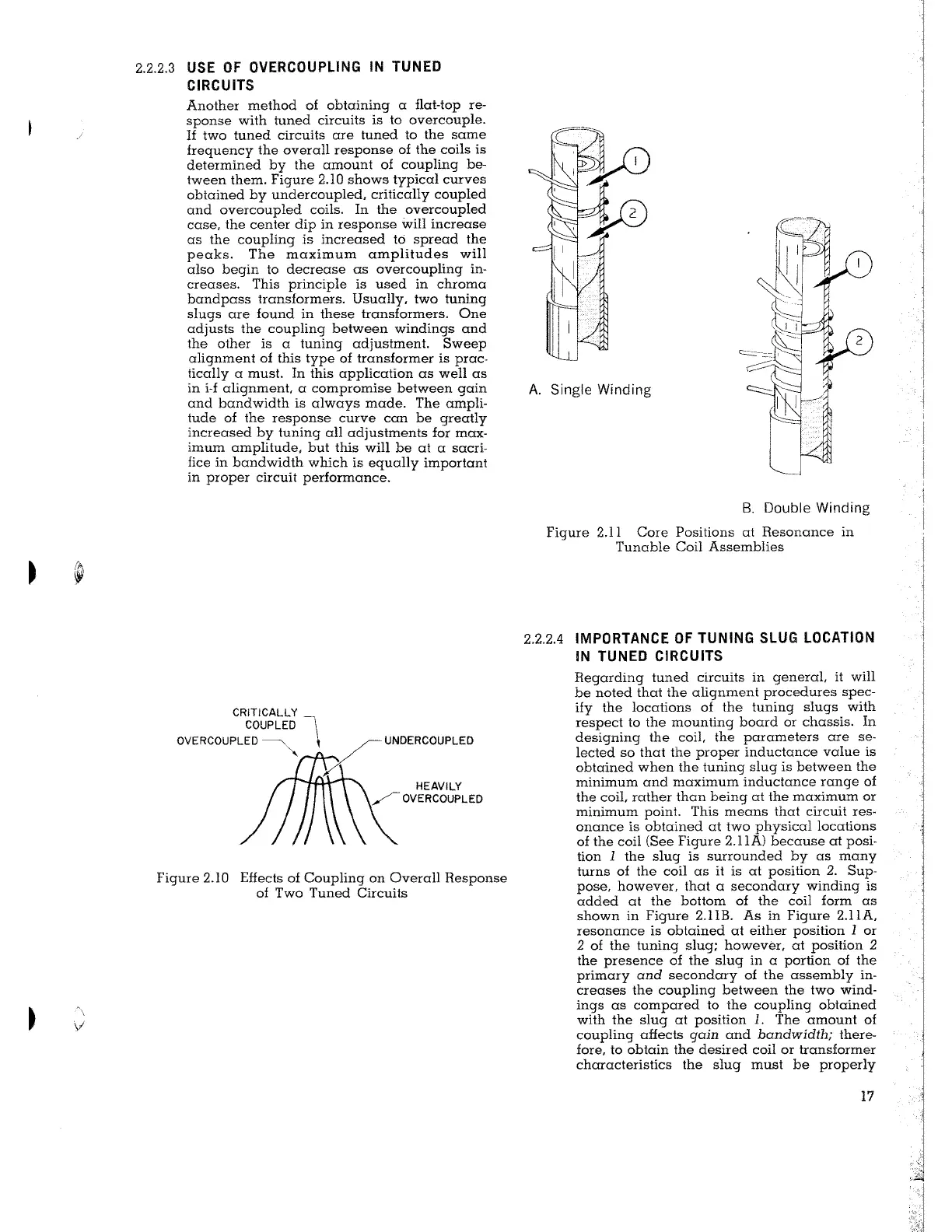
A. Single Winding
B. Double Winding
Figure 2.11 Core Positions at Resonance in
Tunable Coil Assemblies
2.2.2.4 IMPORTANCE OF TUNING SLUG LOCATION
IN TUNED CIRCUITS
Regarding tuned circuits in general, it will
be noted that the alignment procedures spec-
ify the locations of the tuning slugs with
respect to the mounting board or chassis. In
designing the coil, the parameters are se-
lected so that the proper inductance value is
obtained when the tuning slug is between the
minimum and maximum inductance range of
the coil, rather than being at the maximum or
minimum point. This means that circuit res-
onance is obtained at two physical locations
of the coil (See Figure 2.llA) because at posi-
tion
1 the slug is surrounded by as many
turns of the coil as it is at position
2. Sup-
pose, however, that a secondary winding is
added at the bottom of the coil form as
shown in Figure 2.1IB. As in Figure 2.llA,
resonance is obtained at either position
1 or
2 of the tuning slug; however, at position 2
the presence of the slug in a portion of the
primary and secondary of the assembly in-
creases the coupling between the two wind-
ings as compared to the coupling obtained
with the slug at position
1. The amount of
coupling
afiects gain and bandwidth; there-
fore, to obtain the desired coil or transformer
characteristics the slug must be properly
17