12.4.5.1 USING THE SPARE MKR OSCILLATOR AS
A CRYSTAL-CONTROLLED MARKER
OSCILLATOR
The oscillator circuit will accept a third
overtone crystal in the 35 MHz to 50 MHz
range. The crystal pin receptacles provided
accept a crystal in the HC 25/U holder
which has .040" diameter pins. Crystals in
other holder configurations must be wired
into the circuit. For best frequency correla-
tion, the crystal frequency should be spec-
ified with 32 picofarad load capacitance.
The frequency adjustments (C2 and LI) can
be loco.\ea. 'l.n. 'Equ.,:e l?..'2.. 1'.,:\.mme,: co:£)0.C-
itor C2 is a rough frequency adjustment
and tunable inductor LI is used for final
oscillator peaking. When a crystal is to be
used at the low-frequency end of the tuning
range, C2 is set toward maximum capac-
itance and 11 is adjusted for maximum
oscillator output. Minimum C2 capacitance
is used at the high-frequency end of the
tuning range.
To observe the effect of tuning the oscillator,
connect the Model 415 to an oscilloscope as
shown in Figure 5.2 and place the FUNC-
TION switch in the IF position. Set sweep
width to maximum and adjust the sweep
center frequency so that the sweep range
includes the spare marker frequency. With
the CENTER FREQUENCY control set at the
low-frequency limit the sweep range is
about 34 MHz to 45 MHz. With the CENTER
FREQUENCY control at the high-frequency
limit, the sweep range is about 42 MHz to
54 MHz. Set the MARKER AMPLITUDE con-
trol for suitable marker height as determined
from observation of the standard internal
markers. Adjust 11 and C2 as required to
produce a marker indication on the scope.
Adjust 11 for final peaking (maximum
marker height) and then readjust 11 one
turn counterclockwise from the maximum
indication. The marker frequency can then
be used in the 415 post-injection marker
system. The marker signal is also available
at the RF-IF-VIDEO jack when the FUNC-
TION switch is in the MKR or MOD MKR
positions.
12.4.5.2 USING THE SPARE MARKER OSCILLATOR
I\~ I\ \JI\R\~Slt. fRt.Q.UE~CY SOURCE
Although the primary function of the
spare marker oscillator has been outlined
in paragraph 12.4.5, the variable frequency
feature can also be used effectively if a
non-standard marker frequency is desired
anywhere in the i-f sweep range of the
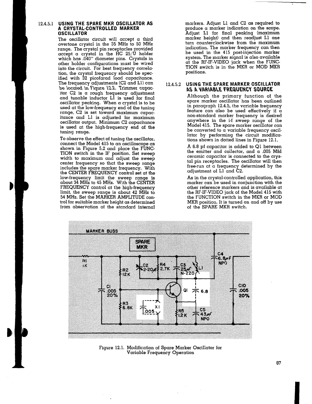
Model 415. The spare marker oscillator can
be converted to a variable frequency oscil-
lator by performing the circuit modifica-
tions shown in dotted lines in Figure 12.1.
A 6.8 pf capacitor is added to Ql between
the emitter and collector, and a .005 Mfd
ceramic capacitor is connected to the crys-
tal pin receptacles. The oscillator will then
free-run at a frequency determined by the
adjustment of 11 and C2.
As in the crystal-controlled application, this
marker can be used in conjunction with the
other reference markers and is available at
the RF-IF-VIDEO jack of the Model 415 with
the FUNCTION switch in the MKR or MOD
MKR position.
It is turned on and off by use
of the SP ARE MKR switch.
Figure 12.1. Modification of Spare Marker Oscillator for
Variable Frequency Operation
87
I