5.2.9
5.3
5.3.1
5.3.2
Most preliminary alignment procedures sug-
gest that the horizontal output circuits of the
TV receiver be disabled to eliminate hori-
zontal frequency interference during align-
fent. This is not necessary when using the
Model 415 because a 15,750 Hz filter has
been inserted in the signal path to the
SCOPE VERT INPUT jack which reduces
any horizontal frequency
"grass" to negli-
gible level. Other alignment set-ups require
removal of the horizontal output tube (or
transistor), or opening the cathode lead of
the horizontal output tube if a series heater
string is used. The B+ line must then be
loaded with external resistors to compen-
sate for the decrease in drain. (DO NOT
DISABLE THE HO RIZO NT AL OUTPUT CIR-
CUIT BY REMOVING THE PLATE CAP OF
THE HORIZONTAL OUTPUT TUBE. This will
cause excessive screen dissipation and may
permanently damage the tube.).
NOTE
The user must keep in mind the fact that,
with the horizontal circuits operating, the
boosted
B+ voltages are present as well
as the high voltage which is 25,000 volts for
color receivers.
USE OF MODEL 415 CONTROLS
As outlined in Par 3.8 all markers are avail-
able on all sweep ranges, except in the 10.7
MHz position in which only the 10.7 MHz
marker and the 100 KHz markers are avail-
able. Because post injection is used, the
markers are visible on the oscilloscope trace
regardless of whether or not a receiver re-
sponse curve is being viewed. Some gen-
eral rules follow.
Always set SWEEP WIDTH control at max-
imum clockwise when setting up.
Turn on the ADJ PIX (39.75 MHz) marker
and the ADJ SND (47.25 MHz) marker. Use
the CENTER FREQUENCY control to center
the sweep pattern as shown in Figure 5.3.
With this setting the entire i-f response will
be included in this range (Figure 5.4).
ADJ PIX
39.75
ADJ SND
47.25
Figure 5.3 Centering Sweep Range by Use of
ADJ PIX and ADJ SND Markers
44
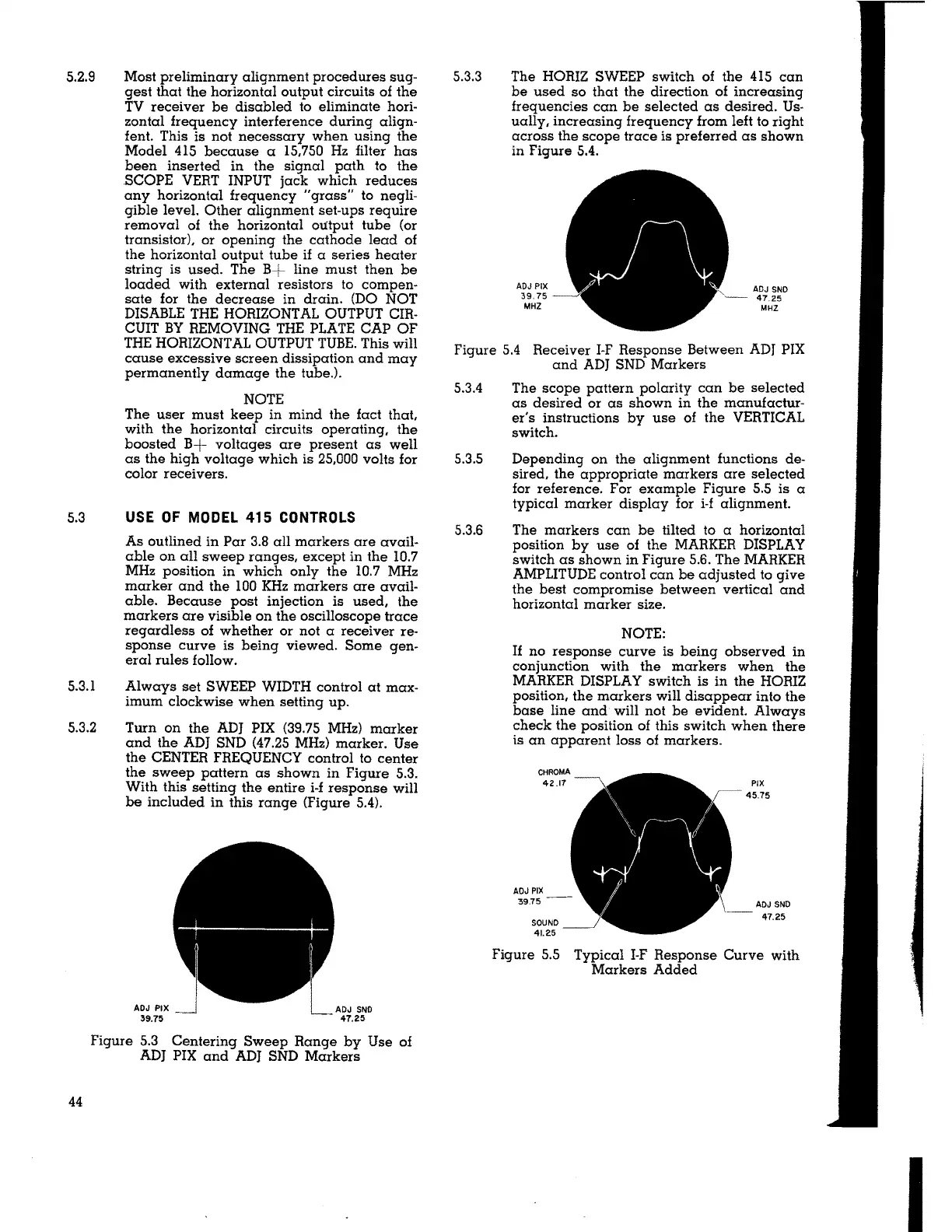
5.3.3 The HORIZ SWEEP switch of the 415 can
be used so that the direction of increasing
frequencies can be selected as desired. Us-
ually, increasing frequency from left to right
across the scope trace is preferred as shown
in Figure 5.4.
ADJ PIX
39. 75
MHZ
J\
ADJ SND
47.25
MHZ
Figure 5.4 Receiver I-F Response Between ADJ PIX
and ADJ SND Markers
5.3.4 The scope pattern polarity can be selected
as desired or as shown in the manufactur-
er's instructions by use of the VERTICAL
switch.
5.3.5 Depending on the alignment functions de-
sired, the appropriate markers are selected
for reference. For example Figure 5.5 is a
typical marker display for i-f alignment.
5.3.6 The markers can be tilted to a horizontal
position by use of the MARKER DISPLAY
switch as shown in Figure 5.6. The MARKER
AMPLITUDE control can be adjusted to give
the best compromise between vertical and
horizontal marker size.
NOTE:
If no response curve is being observed in
conjunction with the markers when the
MARKER DISPLAY switch is in the HORIZ
position, the markers will disappear into the
base line and will not be evident. Always
check the position of this switch when there
is an apparent loss of markers.
CHROMA
42.17
ADJ PIX
39.75
SOUND
41.25
PIX
45.75
ADJ SNO
47.25
Figure 5.5 Typical 1-F Response Curve with
Markers Added
I