11.0
11.l
ll.l.l
OTHER USES OF THE MODEL 415
Because of the inherent versatility and flex-
ibility of the Model 415 there are many ap-
plications and uses of this instrument over
and above basic alignment of television re-
ceivers. The capability for the alignment of
f-m receiver i-f and discriminator circuits
have been designed into the Model 415 and
the use of this instrument in f-m receiver
alignment will be outlined in detail. In ad-
dition, other applications of the Model 415
will be outlined briefly. As the user devel·
ops familiarity with the Model 415 and be-
comes progressively more experienced in
its use and the various features,
it is certain
that he will develop other applications for
use of this instrument over and above those
outlined in this manual.
ALIGNMENT OF FM RECEIVERS USING
THE MODEL 415
10.7 MHz 1-F ALIGNMENT
In this type alignment as in the preceding
sections on television receiver i-f alignment,
it is important to first read the alignment
procedure and locate all test points and
signal injection points, both physically on
the chassis as well as on the schematic dia-
gram. In this way the operator will accu-
mulate experience in performing the vari-
ous i-f alignment tasks and once again
recognize the similarity in the procedures
regarding various manufacturers. Align-
ment of 10.7
MHz i-f sections of f-m receiv-
ers is considerably less involved than the
alignment procedures outlined in the tele·
vision section of this manual. Invariably
the sweep voltage is injected in the region of
the mixer, sometimes at the mixer grid (or
base,
if transistorized) of the receiver. The
monitoring probe is connected at one test
point for performing i-f alignments and is
reconnected at a second test point when
performing discriminator alignment. Pro-
ceed as follows (See Figure 4.21, Repeated.):
41~ SIGNAL
INPUT {75n)
j
1-F
AMPLtFIERS
1-F
BIAS
USE DIRECT
PROB£
Figure 4.21 (Repeated) Typical F-M Receiver
Block Diagram
78
ll.1.1.l Place FUNCTION switch of Model 415 to
10.7 MHz position.
11.1.1.2 Set the SWEEP
WIDTH control to maximum
and use the CENTER FREQUENCY control
to set the dial indicator at the 10.7
MHz sec-
tion of the dial calibration.
11.1.1.3 Set the ATTENUATOR control to minimum
and connect the r-f output of the Model 415
to the 10.7 MHz injection point of the tuner.
Use the 75-ohm termination.
11.1.1.4 Connect the direct cable of the Model 415
to the i-f alignment test point as determined
from the alignment procedure.
11.1.1.5 Place the PROBES switch to the DIRECT
position.
11.1.1.6 Increase the marker amplitude control as
required to observe the 10. 7 MHz marker
which is automatically energized when the
10.7 MHz function is selected. Use the CEN-
TER FREQUENCY control to center the 10.7
MHz marker on the oscilloscope trace.
11.1.1.7 Adjust the ATTENUATOR as required to
produce the required peak-to-peak response
amplitude on the oscilloscope.
11.1.1.8 Reduce the sweep width as required, at the
same time using the CENTER FREQUENCY
control to keep the 10.7 MHz marker cen-
tered on the oscilloscope trace.
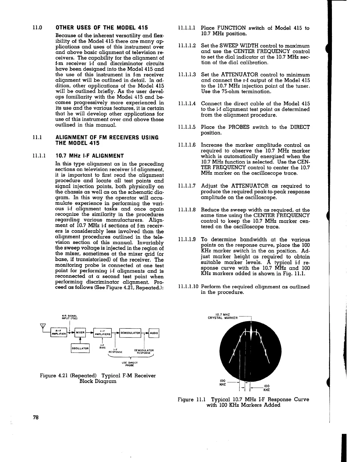
11.1.1.9 To determine bandwidth at the various
points on the response curve, place the 100
KHz marker switch in the on position. Ad-
just marker height as required to obtain
suitable marker levels. A typical
i-f re-
sponse curve with the 10.7 MHz and 100
KHz markers added is shown in Fig. 11.1.
11.1.1.10 Perform the required alignment as outlined
in the procedure.
10.7 MHZ
CRYSTAL MARKER
Figure l l.l Typical 10.7 MHz I-F Response Curve
with 100 KHz Markers Added
I