5.2
5.2.1
5.2.2
5.2.3
EQUIPMENT INTERCONNECTION AND
SET-UP PROCEDURE
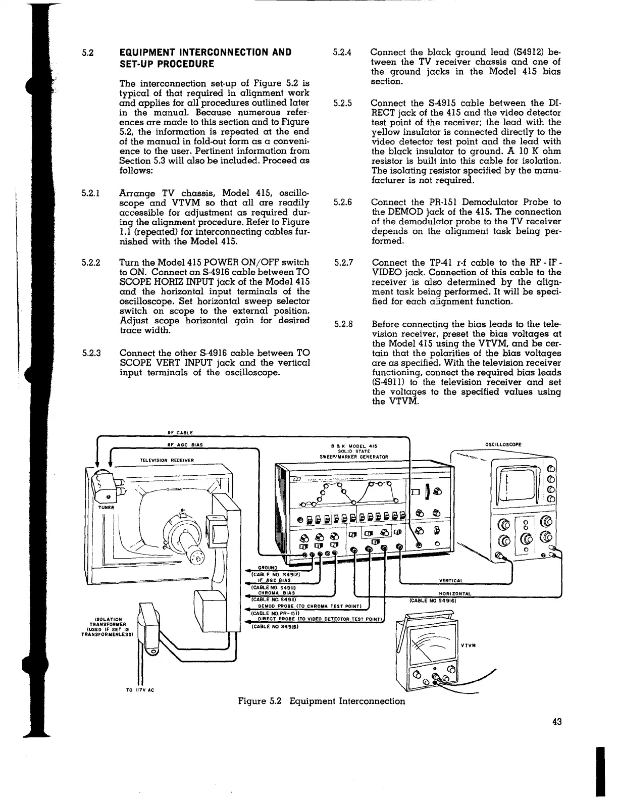
The interconnection set-up of Figure 5.2 is
typical of that required in alignment work
and applies for all procedures outlined later
in the manual. Because numerous refer-
ences are made to this section and to Figure
5.2, the information is repeated at the end
of the manual in fold-out form as a conveni-
ence to the user. Pertinent information from
Section 5.3 will also be included. Proceed as
follows:
Arrange TV chassis,
Model 415, oscillo-
scope and
VTVM so that all are readily
accessible for adjustment as required dur-
ing the alignment procedure. Refer to Figure
1.1 (repeated) for interconnecting cables fur-
nished with the Model 415.
Turn the Model 415 POWER ON/OFF switch
to ON. Connect an S-4916 cable between TO
SCOPE HORIZ INPUT jack of the Model 415
and the horizontal input terminals of the
oscilloscope. Set horizontal sweep selector
switch on scope to the external position.
Adjust scope horizontal gain for desired
trace width.
Connect the other S-4916 cable between TO
SCOPE VERT INPUT jack and the vertical
input terminals of the oscilloscope.
Rf CABLE
RF AGC SIAS
TELEVISION RECEIVER
GROUND
(CABLE NO. S4912)
fF AGC BIAS
(CABLE NO. S4911)
CHROMA BIAS
(CABLE NO. S4911)
5.2.4
Connect the black ground lead (S4912) be-
tween the TV receiver chassis and one of
the ground jacks in the Model 415 bias
section.
5.2.5 Connect the S-4915 cable between the DI-
RECT jack of the 415 and the video detector
test point of the receiver; the lead with the
yellow insulator is connected directly to the
video detector test point and the lead with
the black insulator to ground. A 10 K ohm
resistor is built into this cable for isolation.
The isolating resistor specified by the manu-
facturer is not required.
5.2.6
Connect the PR-151 Demodulator Probe to
the DEMOD jack of the 415. The connection
of the demodulator probe to the TV receiver
depends on the alignment task being per-
formed.
5.2.7 Connect the TP-41 r-f cable to the RF - IF -
VIDEO jack. Connection of this cable to the
receiver is also determined by the align-
ment task being performed. It will be speci-
fied for each alignment function.
5.2.8 Before connecting the bias leads to the tele-
vision receiver, preset the bias voltages at
the Model 415 using the VTVM, and be cer-
tain that the polarities of the bias voltages
are as specified. With the television receiver
functioning, connect the required bias leads
(S-4911) to the television receiver and set
the voltages to the specified values using
the VTVM.
8 a K MODEL 41S
SOLID STATE
SWEEP/MARKER GENERATOR
OSCILLOSCOPE
[Ji
@~o ,@
© ®@
ol
-
~='~
VERTICAL _J
HORIZONTAL
(CABLE NO. S4916)
OEMOO PROBE tTO CHROMA TEST POINT)
ISOLATION
TRANSFORMER
{USED IF SET IS
TRANSFORMERLESS)
TO 117V AC
(CABLE NO.PR-151)
DIRECT PROBE {TO VIDEO DETECTOR TEST POINT)
(CABLE NO S4915)
Figure 5.2 Equipment Interconnection
43
I