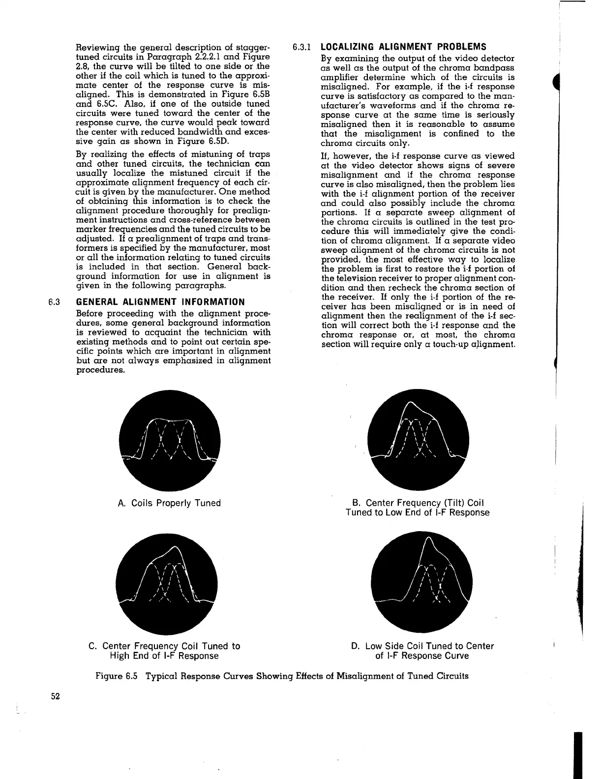
Reviewing the general description of stagger-
tuned circuits in Paragraph 2.2.2.1 and Figure
2.8, the curve will be tilted to one side or .the
other if the coil which is tuned to the approxi-
mate center of the response curve is mis-
aligned. This is demonstrated in Figure 6.5B
and 6.5C. Also, if one of the outside tuned
circuits were tuned toward the center of the
response curve, the curve would peak toward
the center with reduced bandwidth and exces-
sive gain as shown in Figure 6.5D.
By realizing the effects of mistuning of traps
and other tuned circuits, the technician can
usually localize the mistuned circuit
if the
approximate alignment frequency of each cir-
cuit is given by the manufacturer. One method
of obtaining this information is to check the
alignment procedure thoroughly for prealign-
ment instructions and cross-reference between
marker frequencies and the tuned circuits to be
adjusted. If a prealignment of traps and trans-
formers is specified by the manufacturer, most
or all the information relating to tuned circuits
is included in that section. General back-
ground information for use in alignment is
given in the following paragraphs.
6.3 GENERAL ALIGNMENT INFORMATION
Before proceeding with the alignment proce-
dures, some general background information
is reviewed to acquaint the technician with
existing methods and to point out certain spe-
cific points which are important in alignment
but are not always emphasized in alignment
procedures.
A. Coils Properly Tuned
C. Center Frequency Coil Tuned to
High End of 1-F Response
6.3.1
LOCALIZING ALIGNMENT PROBLEMS
By examining the output of the video detector
as well as the output of the chroma bandpass
amplifier determine which of the circuits is
misaligned. For example,
if the i-f response
curve is satisfactory as compared to the man-
ufacturer's waveforms and if the chroma re-
sponse curve at the same time is seriously
misaligned then
it is reasonable to assume
that the misalignment is confined to the
chroma circuits only.
If, however, the i-f response curve as viewed
at the video detector shows signs of severe
misalignment and if the chroma response
curve is also misaligned, then the problem lies
with the i-f alignment portion of the receiver
and could also possibly include the chroma
portions. If a separate sweep alignment of
the chroma circuits is outlined in the test pro-
cedure this will immediately give the condi-
tion of chroma alignment.
If a separate video
sweep alignment of the chroma circuits is not
provided, the most effective way to localize
the problem is first to restore the i-f portion of
the television receiver to proper alignment con-
dition and then recheck the chroma section of
the receiver. If only the i-f portion of the re-
ceiver has been misaligned or is in need of
alignment then the realignment of the i-f sec-
tion will correct both the i-f response and the
chroma response or, at most, the chroma
section will require only a touch-up
a]ignment.
B. Center Frequency (Tilt) Coil
Tuned to Low End of 1-F Response
D. Low Side Coil Tuned to Center
of 1-F Response Curve
Figure 6.5 Typical Response Curves Showing Effects of Misalignment of Tuned Circuits
52
I
 Loading...