4.2.4 MOD MKR
(Figures 4.12 and 4.13)
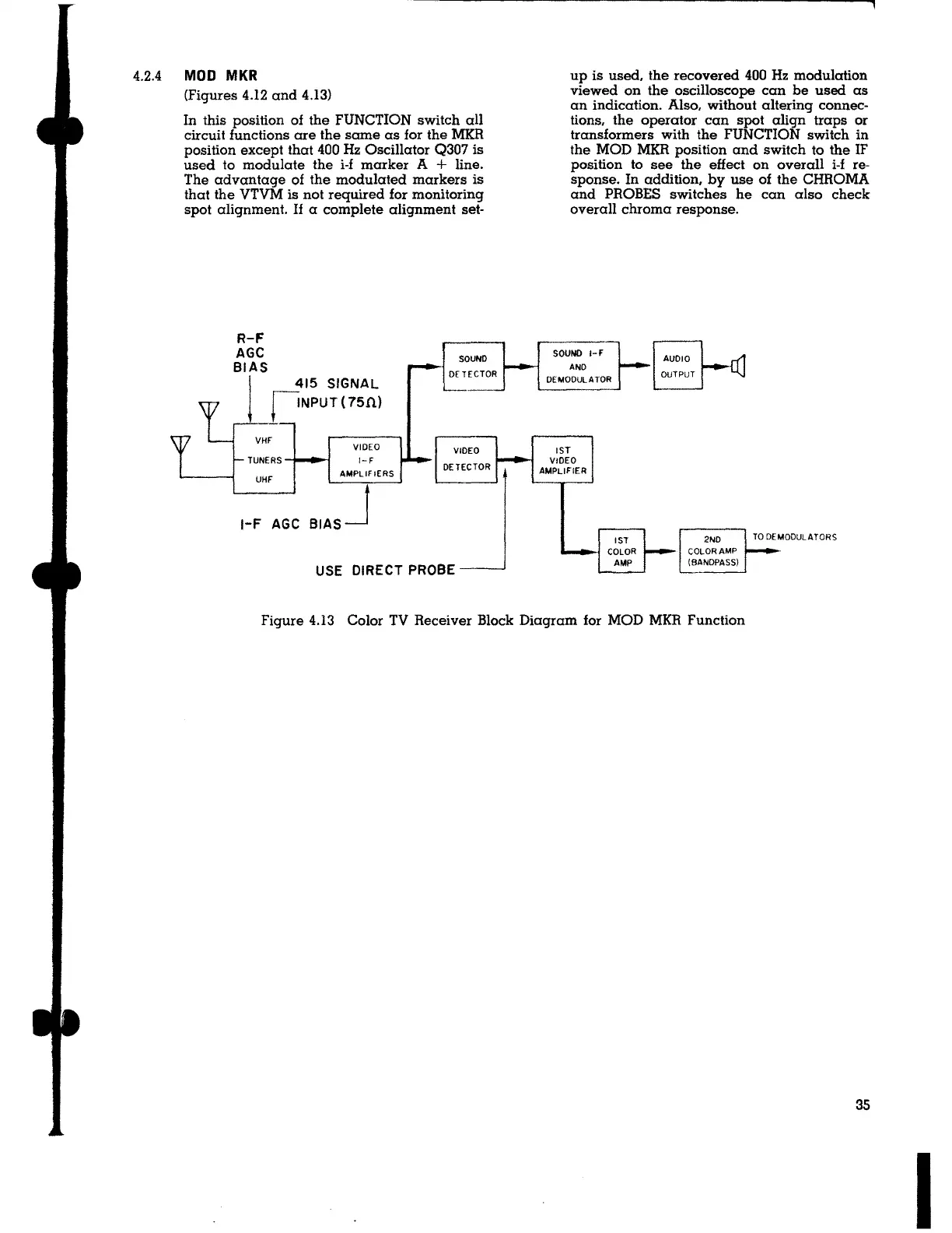
In this position of the FUNCTION switch all
circuit functions are the same as for the MKR
position except that 400 Hz Oscillator Q307 is
used to modulate the i-f marker A
+ line.
The advantage of the modulated markers is
that the VTVM is not required for monitoring
spot alignment.
If a complete alignment set-
415 SIGNAL
f'NPUT (75fi)
TUNERS
UHF
VIDEO
1-F
AMPLIFIERS
1-F AGC BIAS J
SOUND
DETECTOR
VIDEO
DETECTOR
USE DIRECT PROBE _ __,
up is used, the recovered 400 Hz modulation
viewed on the oscilloscope can be used as
an indication. Also, without altering connec-
tions, the operator can spot align traps or
transformers with the FUNCTION switch in
the MOD MKR position and switch to the IF
position to see the effect on overall i-f re-
sponse. In addition, by use of the CHROMA
and PROBES switches he can also check
overall chroma response.
SOUND 1-F
AND
DEMODULATOR
1ST
VIDEO
AMPLIFIER
1ST
COLOR
AMP
AUDIO
OUTPUT
2ND
COLOR
AMP
(BANDPASS)
Figure 4.13 Color TV Receiver Block Diagram for MOD MKR Function
35
I