8.3.5 Recheck instructions for bias requirements
and apply accordingly. Turn on the ADJ PIX
(39.75 MHz) marker and the ADJ SND (47.25
MHz) marker, and, using the CENTER FRE-
QUENCY control, center the sweep on the os-
cilloscope pattern. Adjust marker amplitude
as required using the MARKER AMPLITUDE
control. Make sure that the MARKER DIS-
PLAY switch is in the VERT position.
8.3.6 Turn on the receiver and allow several min-
utes warm-up time. Adjust the RF -IF -VIDEO
ATTENUATOR for a specified signal level
observed on the oscilloscope. Turn on the
PIX (45.75) and the CHROMA (42.17) markers.
8.3.7 Adjust the mixer output tuning adjustment
together with the i-f input adjustment of the
tuner link to obtain the required bandwidth
for the tuner link response. As previously
mentioned the adjustment at the mixer af-
fects the response at the high frequency end
(45.75 MHz) of the curve and the adjustment
at the i-f end of the link affects the low fre-
quency (42.17 MHz) response. A typical tuner
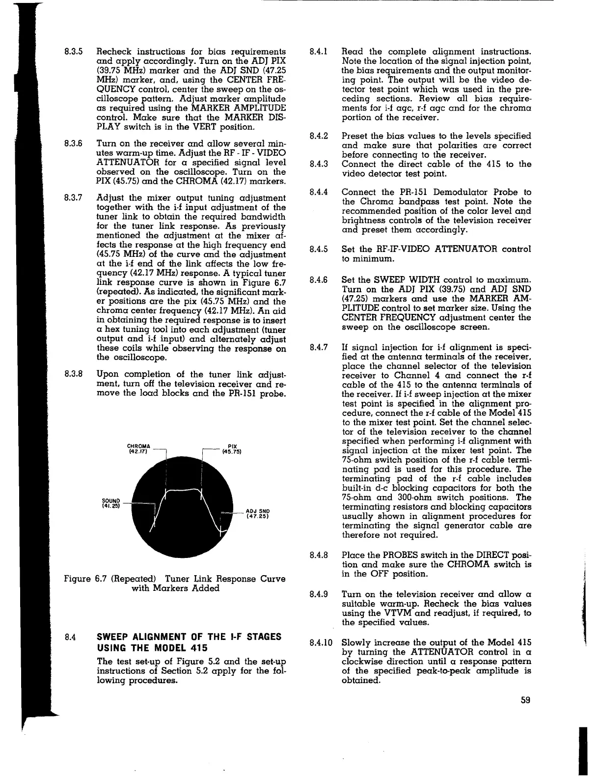
link response curve is shown in Figure 6.7
(repeated). As indicated, the significant mark-
er positions are the pix (45.75 MHz) and the
chroma center frequency (42.17 MHz). An aid
in obtaining the required response is to insert
a hex tuning tool into each adjustment (tuner
output and i-f input) and alternately adjust
these coils while observing the response on
the oscilloscope.
8.3.8 Upon completion of the tuner link adjust-
ment. turn off the television receiver and re-
move the load blocks and the PR-151 probe.
SOUNO
(41.25)
CHROMA
(42.17)
AOJ Sr-ID
(47.25)
Figure 6.7 (Repeated) Tuner Link Response Curve
with Markers Added
8.4
SWEEP ALIGNMENT OF THE 1-F STAGES
USING THE MODEL
415
The test set-up of Figure 5.2 and the set-up
instructions of Section 5.2 apply for the fol-
lowing procedures.
8.4.1 Read the complete alignment instructions.
Note the location of the signal injection point,
the bias requirements and the output monitor-
ing point. The output will be the video de-
tector test point which was used in the pre-
ceding sections. Review all bias require-
ments for i-f age, r-f age and for the chroma
portion of the receiver.
8.4.2 Preset the bias values to the levels specified
and make sure that polarities are correct
before connecting to the receiver.
8.4.3 Connect the direct cable of the 415 to the
video detector test point.
8.4.4 Connect the PR-151 Demodulator Probe to
the Chroma bandpass test point. Note the
recommended position of the color level a~d
brightness controls of the television receiver
and preset them accordingly.
8.4.5 Set the RF-IF-VIDEO ATTENUATOR control
to minimum.
8.4.6 Set the SWEEP WIDTH control to maximum.
Turn on the ADJ PIX (39.75) and ADJ SND
(47.25) markers and use the MARKER AM-
PLITUDE control to set marker size. Using the
CENTER FREQUENCY adjustment center the
sweep on the oscilloscope screen.
8.4.7
If signal injection for i-f alignment is speci-
fied at the antenna terminals of the receiver,
place the channel selector of the television
receiver to Channel 4 and connect the r-f
cable of the 415 to the antenna terminals of
the receiver. If i-f sweep injection at the mixer
test point is specified in the alignment pro-
cedure, connect the r-f cable of the Model 415
to the mixer test point. Set the channel selec-
tor of the television receiver to the channel
specified when performing i-f alignment with
signal injection at the mixer test point. The
75-ohm switch position of the r-f cable termi-
nating pad is used for this procedure. The
terminating pad of the r-f cable includes
built-in d-c blocking capacitors for both the
75-ohm and 300-ohm switch positions. The
terminating resistors and blocking capacitors
usually shown in alignment procedures for
terminating the signal generator cable are
therefore not required.
8.4.8 Place the PROBES switch in the DIRECT posi-
tion and make sure the CHROMA switch is
in the OFF position.
8.4.9 Turn on the television receiver and allow a
suitable warm-up. Recheck the bias values
using the VTVM and readjust,
if required, to
the specified values.
8.4.IO Slowly increase the output of the Model 415
by turning the ATTENUATOR control in a
clockwise direction until a response pattern
of the specified peak-to-peak amplitude is
obtained.
59
I


 To Next Page