5.4
5.4.1
5.4.2
COMPENSATION FOR POOR LOW
FREQUENCY RESPONSE OF THE
OSCILLOSCOPE
If the operator is using an oscilloscope hav-
ing poor low frequency response in con-
junction with the Model 415, erroneous tilt
will be introduced into the response patterns
which is a function of the oscilloscope itself
rather than being a function of the television
receiver which is being aligned. The Model
415 has an internal adjustment which is
used, when required, to compensate for poor
low frequency response of the oscilloscope.
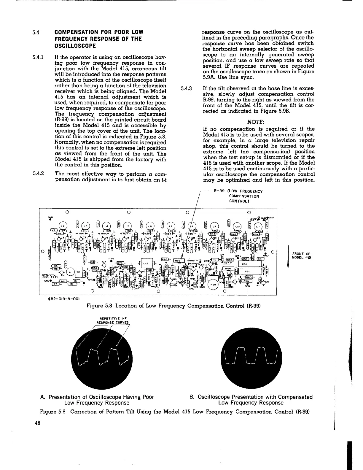
The frequency compensation adjustment
(R-99) is located on the printed circuit board
inside the Model 415 and is accessible by
opening the top cover of the unit. The loca-
tion of this control is indicated in Figure 5.8.
Normally, when no compensation is required
this control is set to the extreme left position
as viewed from the front of the unit. The
Model 415 is shipped from the factory with
the control in this position.
The most effective way to perform a com-
pensation adjustment is to first obtain an i-f
482-019-9-001
5.4.3
response curve on the oscilloscope as out-
lined in the preceding paragraphs. Once the
response curve has been obtained switch
the horizontal sweep selector of the oscillo-
scope to an internally generated sweep
position, and use a low sweep rate so that
several IF response curves are repeated
on the oscilloscope trace as shown in Figure
5.9A. Use line sync.
If the tilt observed at the base line is exces-
sive, slowly adjust compensation control
R-99, turning to the right as viewed from the
front of the Model 415. until the tilt is cor-
rected as indicated in Figure 5.9B.
NOTE:
If no compensation is required or if the
Model 415 is to be used with several scopes,
for example, in a large television repair
shop, this control should be turned to the
extreme left (no compensation) position
when the test set-up is dismantled or if the
415 is used with another scope. If the Model
415 is to be used continuously with a partic-
ular oscilloscope the compensation control
may be optimized and left in this position.
-- R-99 (LOW FREQUENCY
COMPENSATION
CONTROL)
I
FRONT OF
MODEL 415
Figure 5.8 Location of Low Frequency Compensation Control (R-99)
REPETITIVE 1-F
RESPONSE CURVES
A. Presentation of Oscilloscope Having Poor
Low Frequency Response
B. Oscilloscope Presentation with Compensated
Low Frequency Response
Figure 5.9 Correction of Pattern Tilt Using the Model 415 Low Frequency Compensation Control (R-99)
46
I